 Nasser
The project was supposed to be a pneumatic robotic arm, but has been modified into a hydraulic arm, using a water pump instead of an air compressor and air tank! This doesn't change much in terms of design, because like air, water remains a fluid. this note is to avoid any confusion when reading the first project logs
When we started looking for the arm's pneumatic components, we asked ourselves a big question: which components were we going to buy, and which were we going to design and manufacture from scratch? This question mainly concerned the pneumatic actuator, the control valve and the air compressor.
This is our pneumatic schematic for the arm :
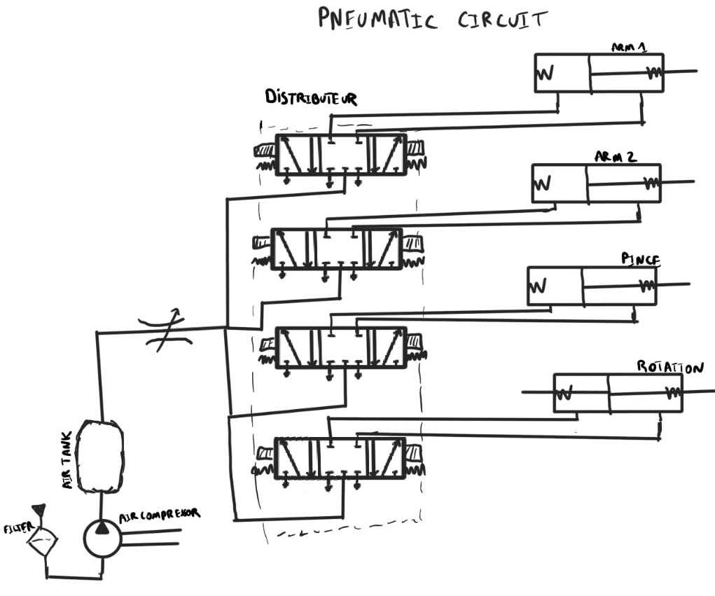
We needed an air compressor with an air tank, 4 closed-center 5/3 control valves and 4 pneumatic actuators.
At first, we decided to try making them ourselves (the actuator, the control valve and even a compressor), we were mostly going to 3D print them.
We were inspired by those video :
| 3d printed air compressor |
| 3d printeed pneumatic actuator |
But after some research based on price and part convenience, we decided to manufacture only one of the three pneumatic components ourselves to save time.
We decided to find and buy a fully manufactured air compressor and pneumatic actuator, but unfortunately, we couldn't find a control valve at a reasonable price and in a size suitable for the project.
So we set about making the 4 5/3 control valves as the first part of the project (which is funny because this is the only component for which we could find any trace of someone making one in 3D).
Discussions
Become a Hackaday.io Member
Create an account to leave a comment. Already have an account? Log In.