This is our second attempt at creating a 3D-printed 5/3 closed-center control valve.
In this iteration, we avoided relying on strict physical principles like magnetism to move the shaft which can be unpredictable. Instead, we opted for a mechanical approach by using a servo motor coupled with a crank mechanism to drive the shaft. This method provides the reliable advantage of a direct mechanical linkage.
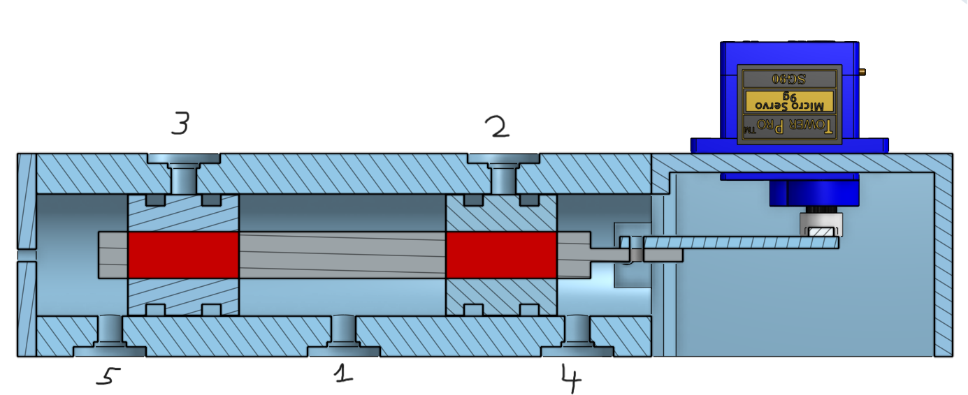
This was our deisgn for this iteration :

- Compressed air inlet
- Air Oultet
- Air Outlet
- Exhaust port
- Exhaust port
The valve consists of a servo motor connected to the shaft via a crank mechanism. The position of the shaft depends on the servo's angle.
It operates as follows:
- Closed position (as shown in the diagram): Servo angle at 90°, blocking all air flow.
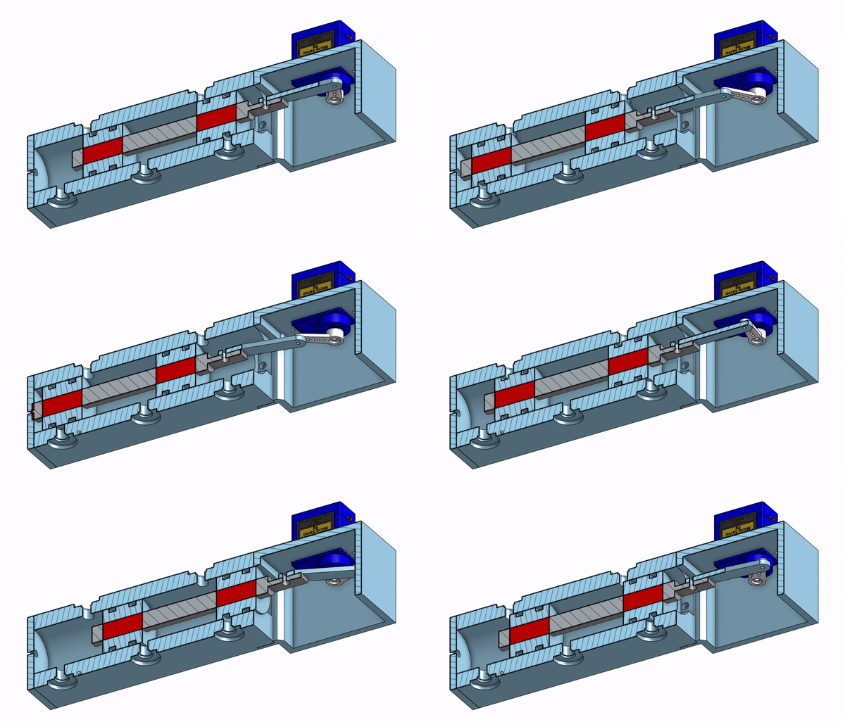
- Right position: Servo angle at 0°, connecting hole 1 → hole 2 and hole 3 → hole 5.
- Left position: Servo angle at 180°, connecting hole 1 → hole 3 and hole 2 → hole 4.
This configuration allows us to control or block air flow as needed.
In the CAD software this was how the valve was supposed to opperate :

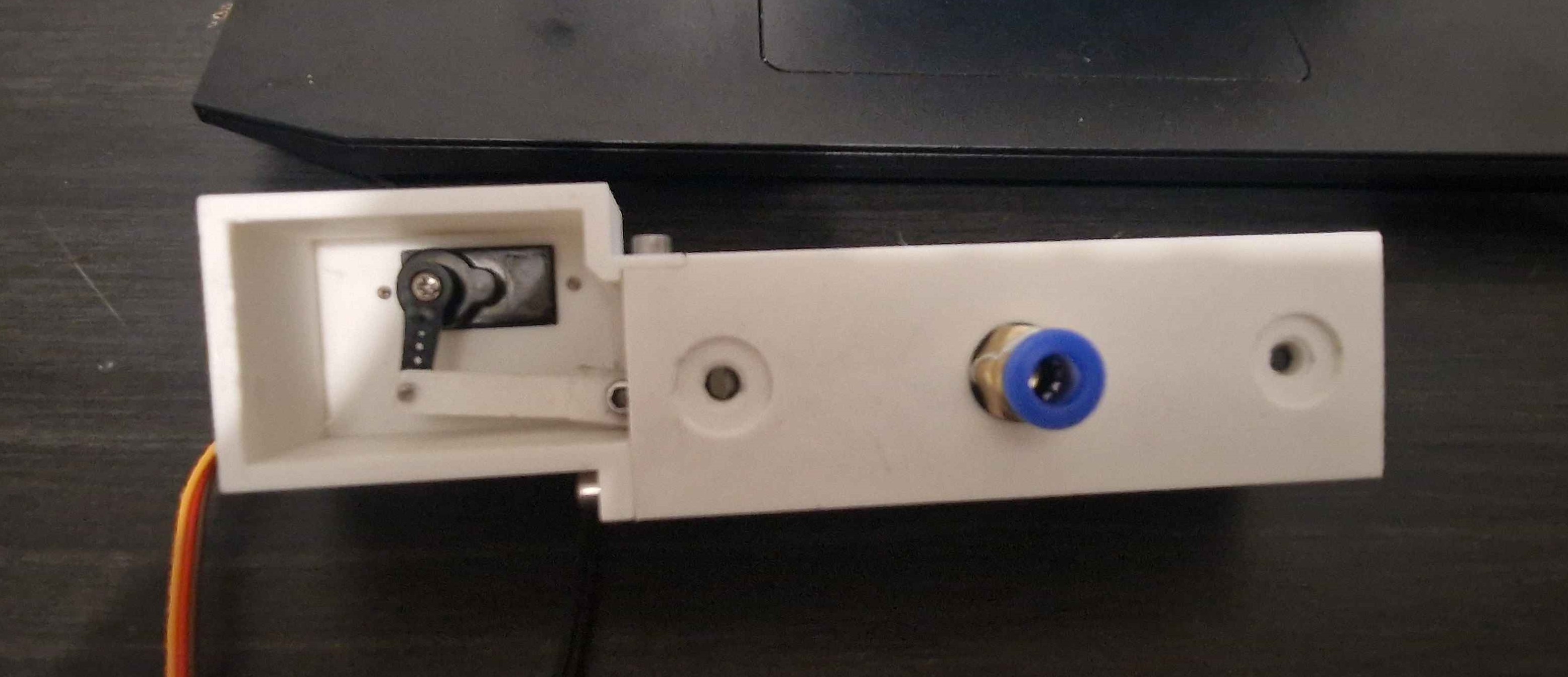
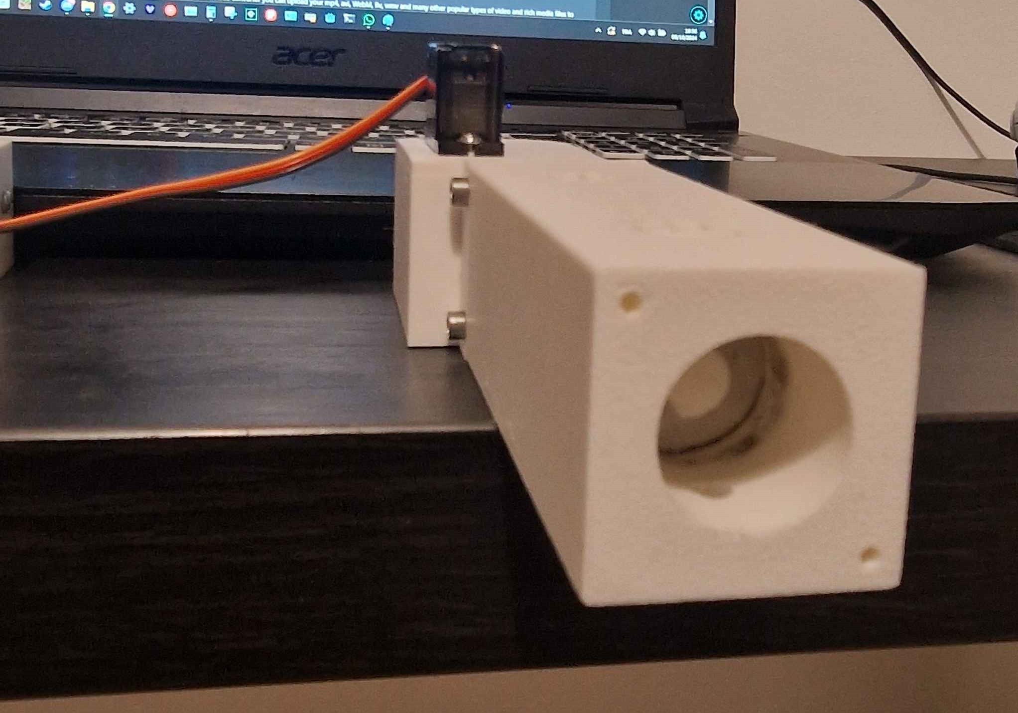
Everything seemed promising, so we decided to build and test the prototype in real life.
 |  |
However, as you might expect, it didn’t perform as well as it did in the CAD animation.
The first issue was that the entire valve was printed in matte PLA, which tends to produce relatively rough surfaces. Adding a sealing ring to the piston on the shaft made movement extremely difficult due to increased friction.
Additionally, our design relied on a 9g servo motor to keep thedesign cheap. Unfortunately, this servo lacked the strength to move the shaft under such high friction conditions, even pushing the shaft with our was already a challenge.
We then decided to change the design once again.
 Nasser
Discussions
Become a Hackaday.io Member
Create an account to leave a comment. Already have an account? Log In.