 Marcrbarker
ADD INTELLIGENCE TO RADAR SENSING
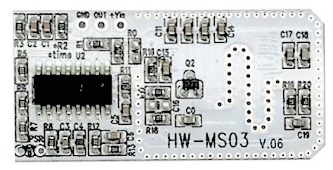
Based on ubitquous HW-MS03 microwave doppler modules, with most of what's here reusable in general for other similar devices. Tackles head-on their quirkyness and sometimes erratic operation.
This is a numbered list of Hints and Tips to get the best out of them, avoid pitfalls and improve performance.
1. INTRO
The manufacturers don't know completely everything about them as they tend to copy a standard circuit in the public domain. A manufacturer datasheet is often the public domain info issued in a PDF along with their logo. If you ask the manufacturer anything technical they tend to ask how many do you want to buy and send you the same generic pdf datasheet with their logo.
Sellers usually just know how to apply power and connect to a Arduino or what other product they sell.
Others like Bigclive.com had taken the trouble to see how they work and try some things out.
This project digs yet deeper and gets underneath the design and the rhetoric going round and ever-cloning itself on the 'Net.
2. OVERVIEW
The idea of simple proximity sensing with RF is donkey-years old, famously used WW2 inside Allied ground-to-air 'flak' proximity shells to trigger at precise moment just passing the aircraft targetted.
This cheap microwave sensor module we're talking about is based on a single transistor microwave oscillator/ 'S' track antenna coupled to the standard IC BISS0001 used in about every PIR sensor light, you know the one with the turny-dials which set the light shine time and how dark outside it must be. The chip is produced in millions and costs probably less than one cent.
3. OUTPUT NOT "LOGIC LEVEL"
Contrary to what the datasheet suggests and what we're continually told including by manufacturers: Output pin 2 does not 'output 0 V' when sensor inactive. When the output isn't H the pin is more like an OPEN CIRCUIT than a L. This can cause phantom 'stuck H' behavior or 'phantom detection' while the sensor is un-triggered.
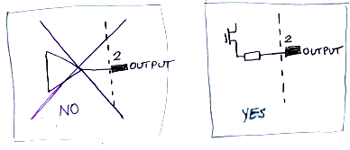
The only reason the output drops towards 0 V is because of what's connected is actually doing this pulling down, whether that's your multitester, scope probe you're measuring it with, or whatever. This is because the BISS0001 IC is for sourcing a current to drive a NPN transistor base. It's an open drain driver not a true logic output and would fail to meet specification if it was. The output does not sink any current. It only takes a few microamps of current to spoil its 'L logic level' / '0V'.
What this means: If you feed the output into a logic input, do not have any pull-up on the input !. So forget trying to connect to a TTL levels input !! Even inadvertantly configuring a microcontroller's weak pull up enabled would stop it working.
Since it's effectively a floating logic input pin while waiting for trigger you might want to add a pull-down R/capacitor, especially if there are high level of RFI around, or line voltage wires nearby.
4. PROXIMITY, DOPPLER, VOLUMETRIC, INDUCTION?
One half of the sensor is a single transistor oscillator / snake antenna at microwave frequency, radiating continuously. The oscillator is not fixed to a specific rigid frequency.
Some of the radiated RF energy comes back to its 'S' antenna. The oscillator becomes influenced by incoming external RF energy, especially so when very near its own oscillation frequency.
That incoming external RF usually comes from its own reflected emissions, (but could come from anywhwere including from another device of that same frequency).
Notes about oscillators and resonance:
A) There is an experiment with metronomes set to very slightly different beat rates, they are coupled with eachother by sharing a single common platform they stand on. The platform underneath wobbles slightly reacting to the movements above. The metronomes passively align their beats to coincide in sync with eachother, so they are in phase.
B) The case of wine glass shatter from a sound playback:- The wineglass vibration frequency pulls itself to and phase locks with the excitation sound frequency. The closer the sound frequency matches the wineglass's resonant frequency, the faster the stored energy builds up to break the glass.
C) Doppler is moreorless detecting difference an incoming variable microwave frequency has to a fixed reference frequency. If simply mixing return signal and oscillator's original signal together, a detected beat note needs much processing. This scheme would be for measuring a detected object's velocity, not simply the movement of it.
So the oscillator is sensitive to external influence on its 'S' antenna. The incoming external energy is usually a reflection of its own microwave emission.
Let's assume then when the oscillator receives this external influence it passively 'pulls' its frequency very slightly so it its own phase aligns itself with the phase of the strongest return signal. Simply by conservation of energy effect within an active circuit. If you've ever used a well built tube-type grid-dip instrument you'll have seen this effect very strongly.
Further assumed therefore oscillator effectively phase-locks itself to an exact frequency that's related to a wavelength multiple that fits the distance of its strongest return signal.
This is similar to how microphone feedback squeal 'hops' between different fixed frequencies as the microphone is moved. Another analogy is shake the end of a rope which has the other end tied to a fixed point, it'll be easiest to shake at a particular frequency related to rope length.
Whatever the case is, changes in reflected microwave energy alter the microwave oscillator transistor's DC current. This change in current is manifests as mV-level disturbances, to be voltage amplified by about 4000x.
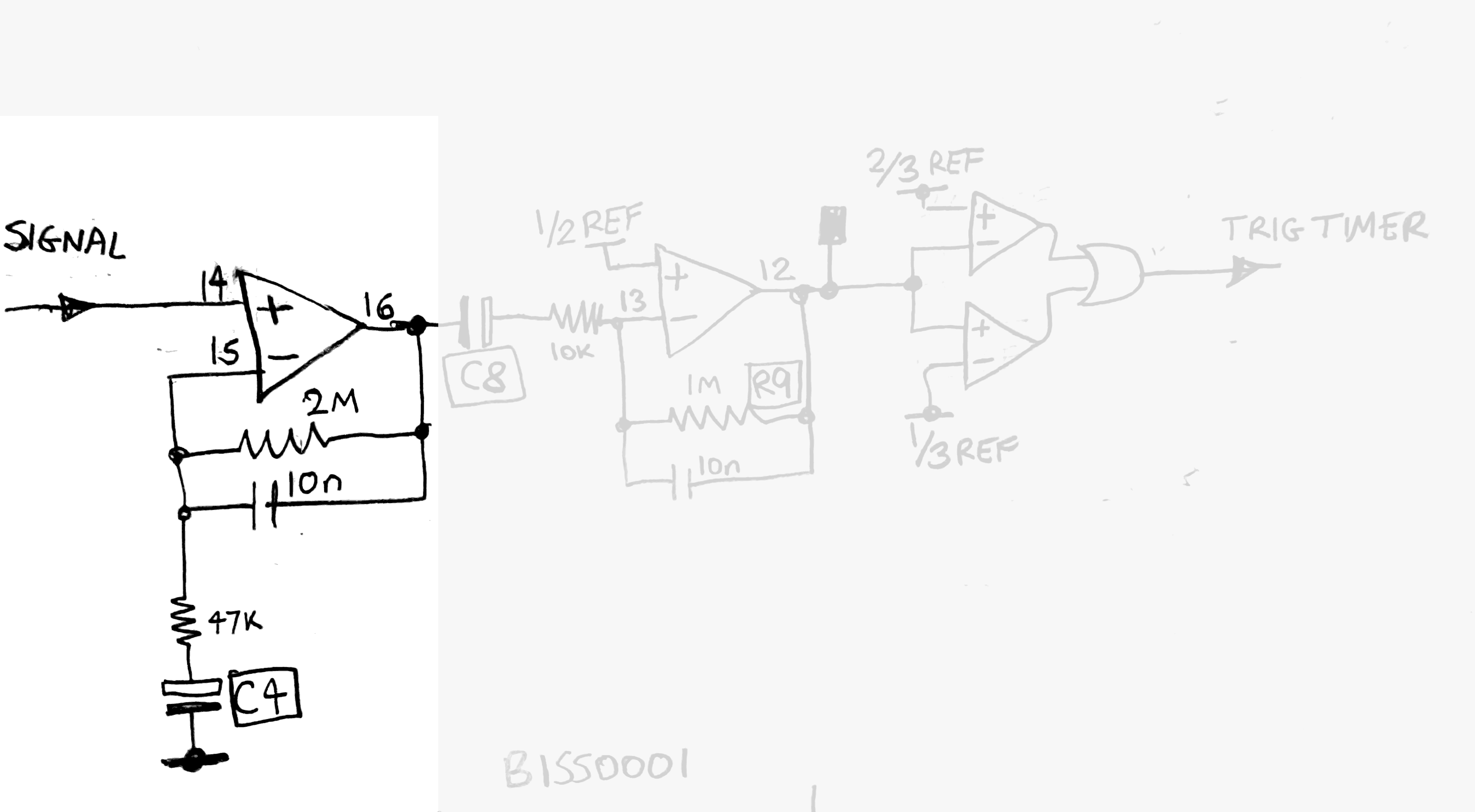
5. SIGNAL AMPLIFICATION STAGE 1
Based on BISS0001 chip originally designed for passive infrared sensor lamp. The analog half of chip contains two opamps, a window comparator programmed by stabilised voltage references.
Signal input pin 14 comes from the mV-level disturbance of the RF oscillator, superimposed on about one volt of DC.
A non-inverting amp of voltage gain of about 400x to slow-changing signals. ( 1+ 2000K / 47K).
Bias point is self-stabilising and this adapts to build tolerances, packaging and mounting influences, thermal effects and aging etc.
Pins 15 & 16 self-stabilise at pin 14's input steady-state voltage, C4 voltage becomes the average of pin 14 voltage, via the 47K.
This self biasing inherently also attenuates slower rate-of-change signals, because the self-stabilisation action consumes them. Seeking a fast stabilisation time thus implies losing detection sensitivity, especially at extended distance range.
Increasing value of C4 increases detection sensitivity to slow-moving and/or distant subjects. 47uF to 100uF guide value. See later note 10 about retrigger delay.
Audio signal and higher frequencies is attenuated down to unity by the 10nF. Higher still frequencies attentuated to zero by opamp's slew-rate limit. This prevents amplifying noise outside of intended detected signal bandwidth.
The idea is to limit bandwidth and only amplify the signal of interest: the slowly-changing DC voltage which comes from object detection. (roughly 1-10 mV / second)
6. SIGNAL AMPLIFY STAGE 2
The second opamp is an inverting amp of about 100x (1000K/10K) to slow-changing signal.
Signal AC-coupled by C8 which also acts as voltage level-translation between stages.
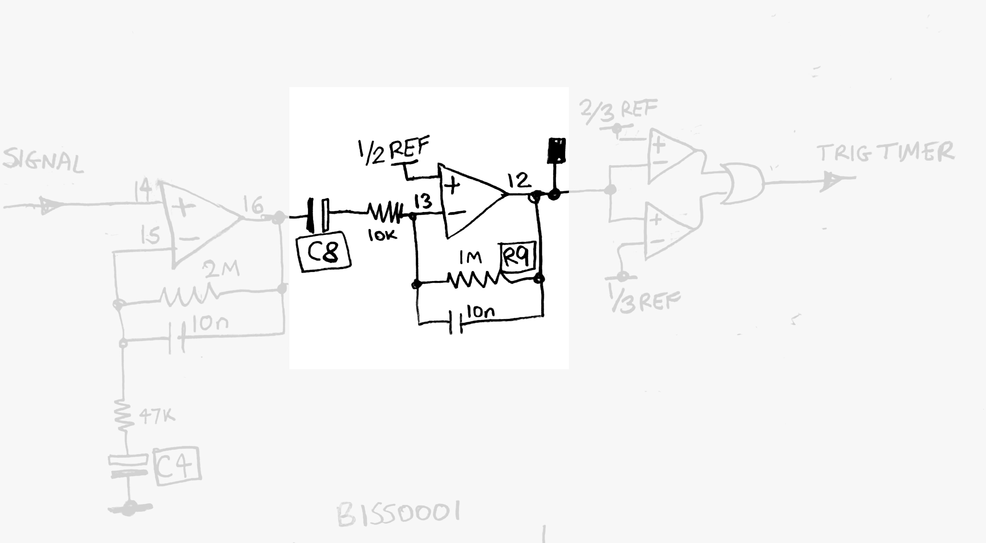
The non-inv input is pegged to 1/2 Vref. This in turn sets the opamp output pin 12 to sit exactly midway between 1/3 Vref and 2/3 Vref.
C8 and 10K effect an increasing reduction of gain of very slow-changing input signals. This in turn reduces detection sensitivity at extended distance.
Increasing value of C8 will increase detection sensitivity to slow-moving and/or distant subjects. 47uF guide value. See later note 10 about retrigger delay.
Audio and higher frequencies (out of band noise) are heavily rejected by 10nF between pins 12 & 13.
7. 'SENSITIVITY' SETTING RESISTOR
Like the PIR sensor lamp's sensitivity control knob, it is R9 here. 1M nominal. Sets gain of second stage. Decreasing its value reduces sensitivity.
Reducing sensitivity with R9 can easily stop the module detecting altogether (other than to very fast subject movement). This is because slower rate-of-change signals are consumed by the action of self-stabilising circuit (C4, C8).
Increasing value of R9 can encourage random triggering due to a random low frequency noise floor present which is only just adequately filtered from the signal.
As mentioned earlier increasing values C4 and C8 greatly increases sensitivity and signal to noise ratio. Adding a 1 M potentiometer in parallel with R9 to reduce gain will likely be needed. (I was picking up vehicles moving in street below from 5th floor window)
See later section: future development.
8. WINDOW COMPARATOR
A 3.0 V approx stabilised voltage is generated on chip. Pin 8. It is potential divided internally into 1/3, 1/2 and 2/3 voltage references. Not shown.
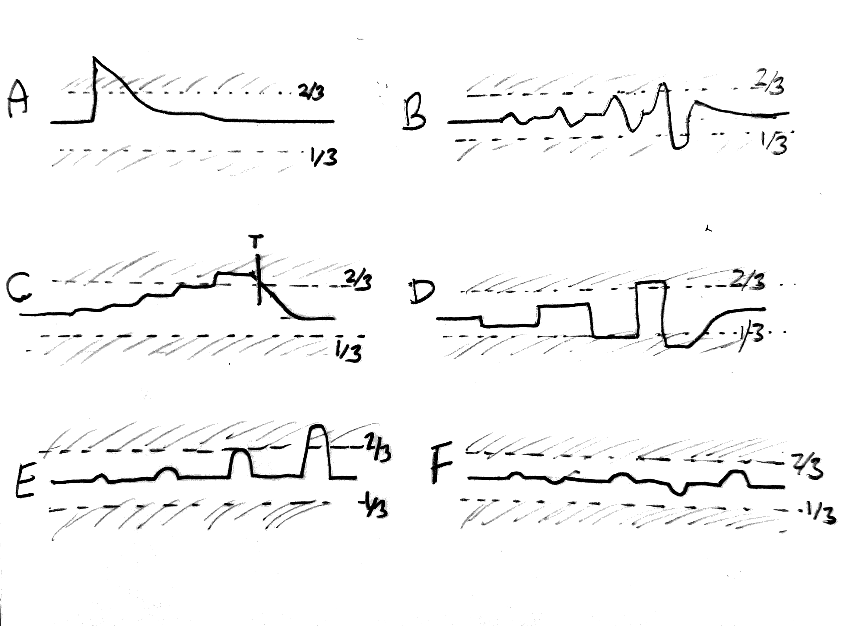
Window comparator included within the IC. At no-detect condition opamp pin 12 sits at 0.5 Vref. During subject movement pin 12 voltage slews up or down and drives the comparator pair inputs
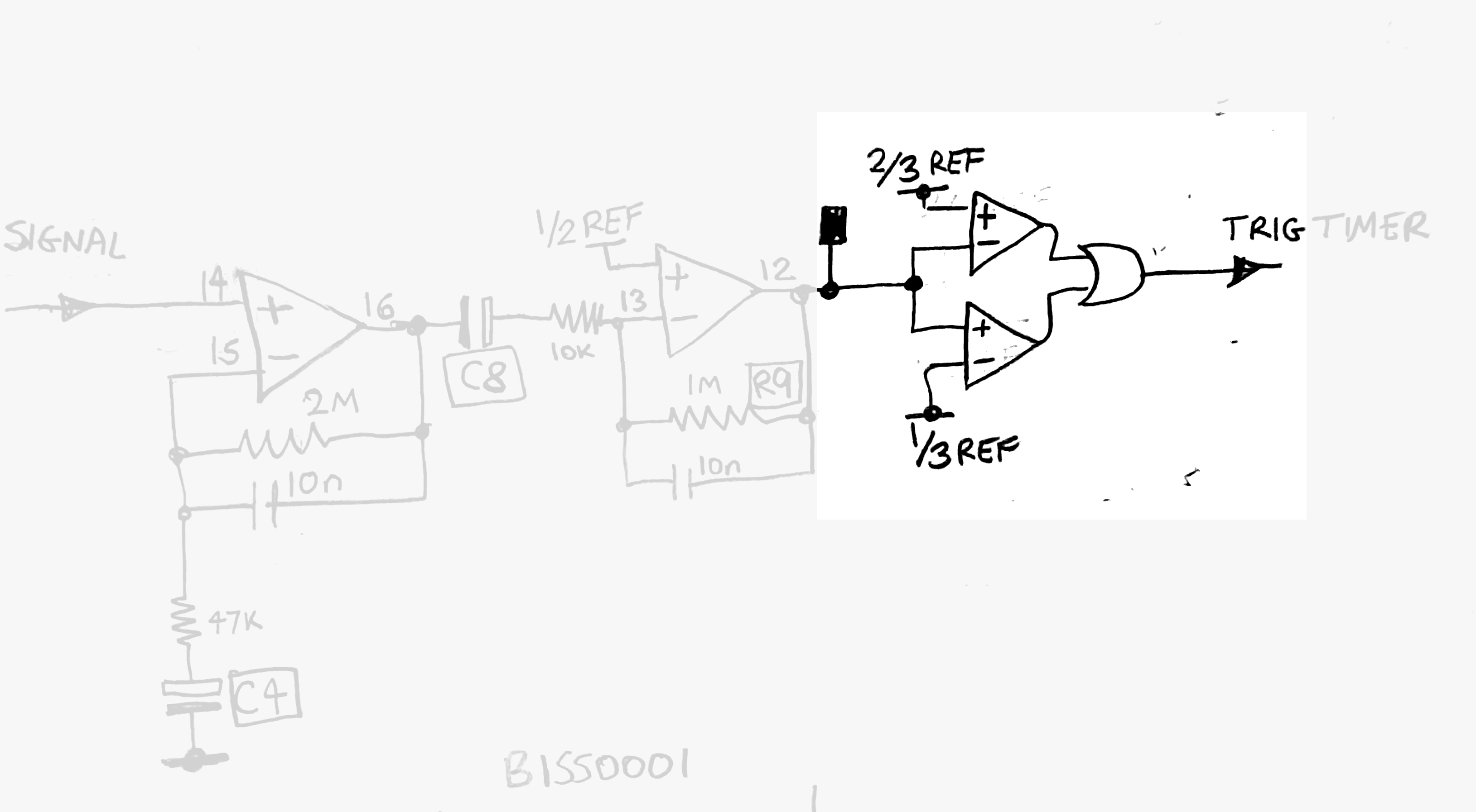
When this voltage exceeds 2/3 Vref or goes below 1/3 Vref this generates a trigger.
9. OUTPUT PULSE-STRETCHING TIMER
This is equivalent to the common PIR light's 'ON' time (from a second to minutes, adjustable with a knob).
The time period of the output is set by values of R and C on pins 3 & 4. These program a low frequency oscillator and counter combination.
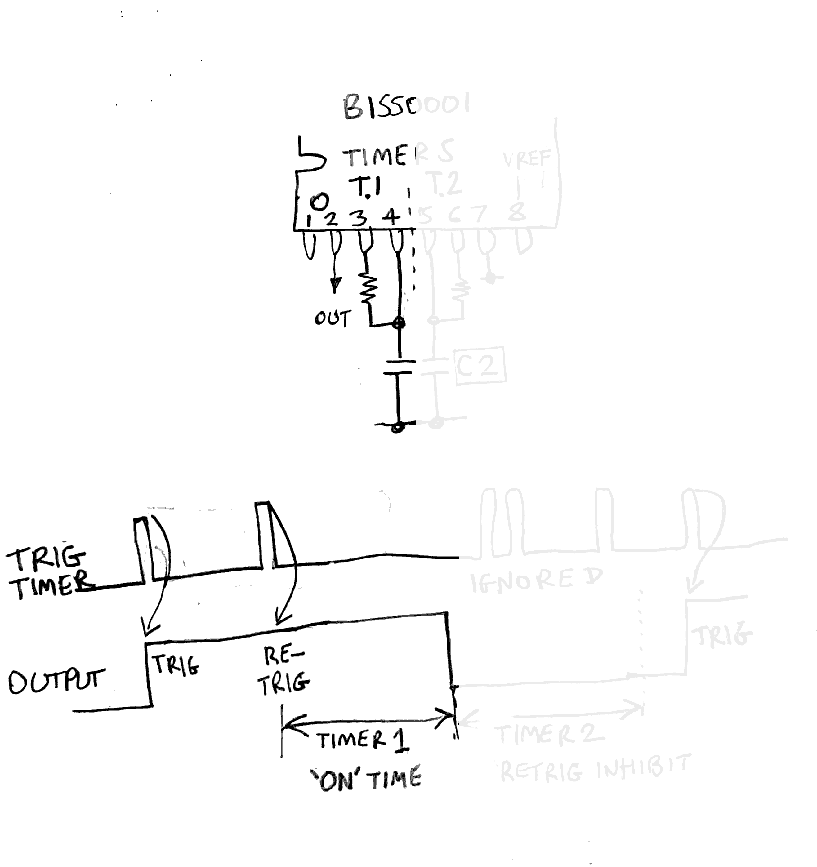
The slower the oscillator the longer the output stays H after the end of the input trigger. Increasing the C reduces the frequency.
On the microwave sensor HW-MS03 it is set to a relatively short time.
10. SENSOR SETTLING AND STABILISATION TIME (PREVENT SELF-TRIGGERING)
On a PIR sensor light, after the timer cuts the power to the halogen lamp, it is still extinguishing. If the movement detector is enabled right away it can get retriggered again by by the lamp turning off.
The BISS0001 IC provides a re-trigger inhibit delay timer, set by the values of R and C2 on pins 5 & 6. The slower the oscillator the longer the re-trigger inhibit time. On the microwave sensor HW-MS03 this is set to a relatively short time.
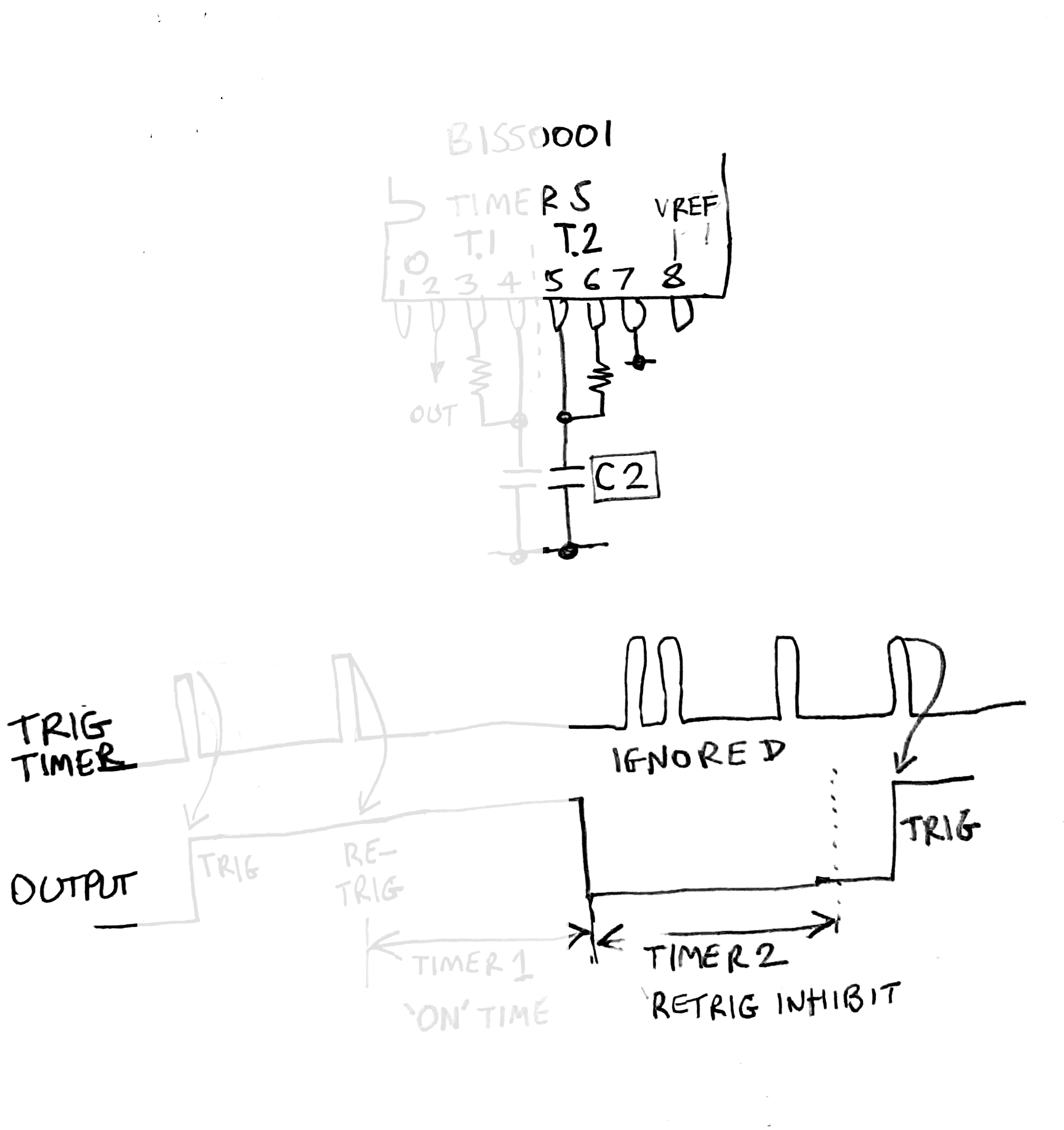
To reliably detect slower moving/distant subjects the time constants C4 and C8 can be increased. This naturally requires a longer stabilisation time (from switch on) which would not be noticeable as only happens once at power up.
However there is a side effect to extending detection range (by processing slower-moving input signal). The input signal on pin 14 suffers a signal saturation jolt when the IC is triggered. After the end of the input trigger stimulus the circuit is still stabilising itself. This can provoke continual self-triggering.
To block the self-triggering the value of C2 may be increased to extend the retrigger enable per. Guide value 0.1uF to 0.47uF.
11. POWER SUPPLY INPUT
The PCB on the HW-MS03 contains a 3.3 V LDO regulator. It has a series diode for reverse-voltage protection. The diode incurs a voltage loss.
When running from a single lithium cell, while less than full charge level and because of the diode drop 0.15 to 0.2 V these combination of factors may not be enough overhead voltage for the LDO to work at its best, affecting stability.
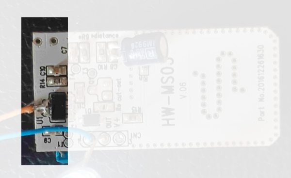
The diode D1 can be bypassed, by connecting the +V feed directly to the LDO's input pin on the edge of the PCB.
12. EXPERIMENTATION AND DEVELOPMENT / TESTING
A good test point is to pin 12 of the BISS0001, the raw input to the Window Comparator.
Ideally connect a scope set to X-Y with the single dot in center of screen. The dot will shift back and forth and easy to differentiate between noise and signal.
An analog display voltmeter set to 5 V or near would be next best thing.
FUTURE PROJECT DIRECTION
Experimentors welcome.
INCREASE SIGNAL / NOISE RATIO
Explore the choice of tradeoffs made with the values.
Were they chosen cheap as possible to make basic as possible performance? From first impression it's optimised to respond most to a person briskly walking up to the door it's located above.
Range doubles by altering values without sacrificing stability, it can repeatibly detect street movement below from a 5th floor window, but these components cost nearly 50 cents more to buy.
AUDIBLE CUE
To monitor the raw signal as a sound. Similar to the sound a Metal Detector makes while detecting an object.
Feed pin 12 into a voltage-to-audio-frequency function, into a sounder. Then do walk tests.
INTELLIGENT SIGNAL PROCESSING
Most of the signal's useful information is discarded just after pin 12, it's only processed by simple a preset threshold window comparator.
Contained within that discarded signal can be deduced the object's direction and relative velocity, perhaps even distance.
Feed pin 12 directly into the A-to-D of microcontroller and sample the value about 10 Hz or higher.
Once in the software domain intelligence DSP can be done. To recognise the signal patterns from the random noise.
Sensitivity fine tuning, and all further signal processing including pulse stretching and retrigger inhibit delay can be under full software control.