 guilldeas
The problem so far
This has to be my biggest repair attempt to date, from the moment I opened it's lid it was apparent that no clear cut solution like swapping dried out PSU caps was gonna get this old guy back in order.
The symptons are simple enough, the multimeter reads 0.00000 Volts regardless of what you plug at it's input or what type of measurement you perform, everything else behaves properly though: Display, firmware version at boot up, switches, etc. This points away from microprocessors, memory, peripherals, etc and suggests the A/D converter might be at fault, thankfully though the owners manual is a gem from the past, the first 79 pages explain how to operate the machine, the following 236 explain how to repair it, you would never dream of such attention to detail nowadays, in fact if you are reading this looking for ways to repair your's I'd advise you to go look at the owners manual instead, you'll find most of what you need there, I will give advice on a couple of matters that you might find helpful though so consider rereading this once you've gone over the manual.
Not only the manual is prepared to thoroughly assist you in your troubleshooting but the machine is too, many test-points are generously layed out in all PCBs, a short-lived technique known as "Signature Analysis" is employed to troubleshoot digital circuits and most importantly a "Self Test" button in the front tells the microprocessor (μP from now on) to test various functionalities in your machine so that you can start troubleshootind, mine gave error at test 7 which does indeed suggests somethings wrong with the A/D converter.
Theory of Operation
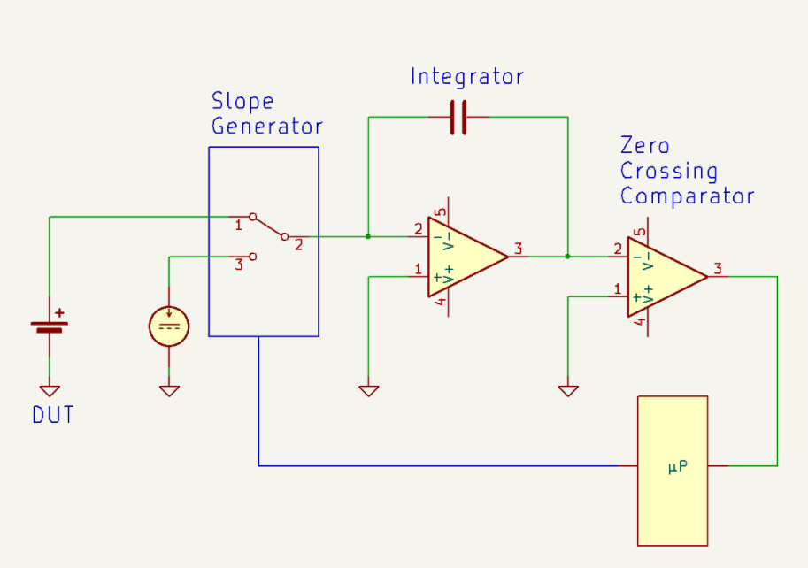
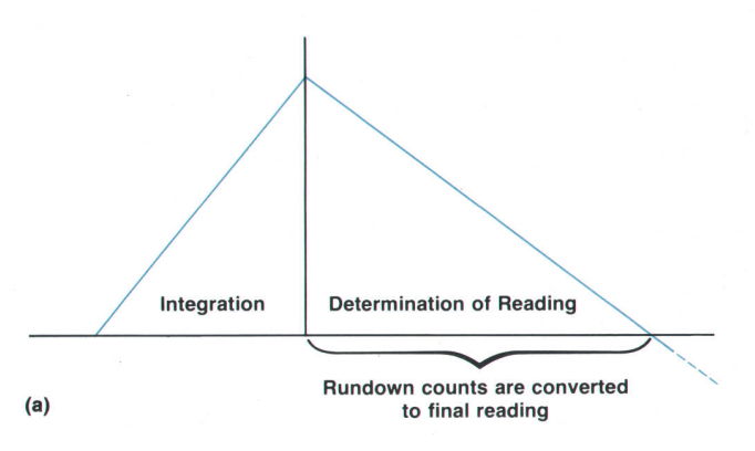
Before following with the troubleshooting attempts let's first summarize the principles of operation for this device. The basic concept behind it's ADC is the "Multi-slope II" technique, to understand it let's build up from the more ubiqutous "Dual slope" technique. This technique pictured on [Fig. 1] measures an input DC voltage by first charging an integrator cap for a fixed amount of time labelled integration in [Fig. 2] this process is what we call "runup", after that time has passed the μP starts counting again clock cycles and switches the input to a "Slope Generator" a precise current source that discharges the charge built up in the integrator cap at a known fixed rate thus dropping the voltage on the cap, finally a "Zero Crossing Comparator" signals the μP when the voltage has reached zero and it stops counting, this is what we call "rundown".
One can understand the operating principle by looking at [Fig. 2], we are essentially comparing our known charging rate against the input charging rate. Another way to look at it is from the perspective of elementary school math, the problem is pythagorean in nature: "knowing the length of the bases and the slope for the right most triangle find the slope for the left most triangle".
This technique is no doubt smart since it makes use of the timing precision in digital electronics that is now ubiqutous everywhere, employing also a precise current source it is able to perform highly accurate measurements, however one can quickly see some problems appear: Say that we want to perform a higher voltage measurement, now the runup slope will be higher, the voltage at the integrator after runup...
Read more »