Notes on MIDI Interface Hardware Development
In June 2024, I completed the hardware for a MIDI interface, but I hadn’t yet documented the process. This blog post will serve as a reference for the design and technical details.
1. Design Approach
Since this was a prototype, I focused on building it quickly by leveraging existing components and minimizing effort. The interface was assembled using the following components:
(1) An ACIA interface board for the RC2014 bus
(2) A MIDI clock generator
(3) A 5mA current loop interface for MIDI
2. Technical Details
(1) ACIA Interface Board for RC2014 Bus
To expand Steve Cousins' SC114 (Z80 Motherboard), I had already created the "61c Serial and Storage board", designed by Karlab, which can be found at (https://oshwlab.com/karlab/61c-serial-and-storage). Since I had a spare board, I decided to make use of it. I just used only the ACIA section, though.
The ACIA can be mapped to the I/O addresses of $80, $90, $A0, or $B0. Since $80 is reserved for the console, I utilized one of the remaining addresses. Additionally, it seems that the Small Computer Monitor (SCM) supports configuration of a second serial port at $A0. In SCM, ACIA is initialized at boot.
(2) MIDI Clock Generator
Generating the required 31,250bps MIDI speed necessitates a 2MHz clock, which cannot be derived from the CPU clock. Fortunately, the board design included a crystal oscillator pattern. While purchasing a 2MHz crystal oscillator would be the easiest solution, I repurposed an AVR TINY202 clock oscillator from a previous project. You can check out the code for that (https://github.com/kuwatay/6809ctrl/blob/main/hardware/6809E-CLOCK/6809E-CLOCK/6809E-CLOCK.ino).
MIDI requires a clock accuracy of ±1%, but using the factory calibration of the TINY202 gives an accuracy of about ±2%. So far, I haven’t encountered any issues, but I plan to replace it with a 2MHz crystal oscillator if needed.
(3) 5mA Current Loop Interface for MIDI
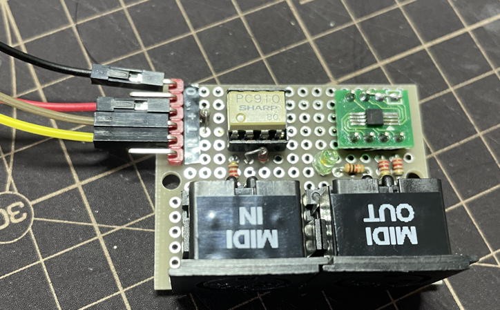
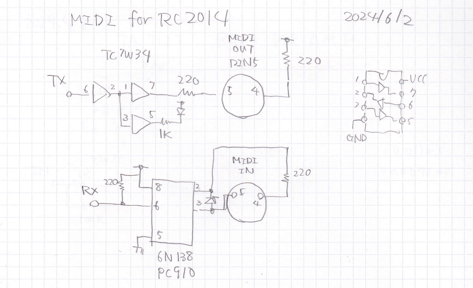
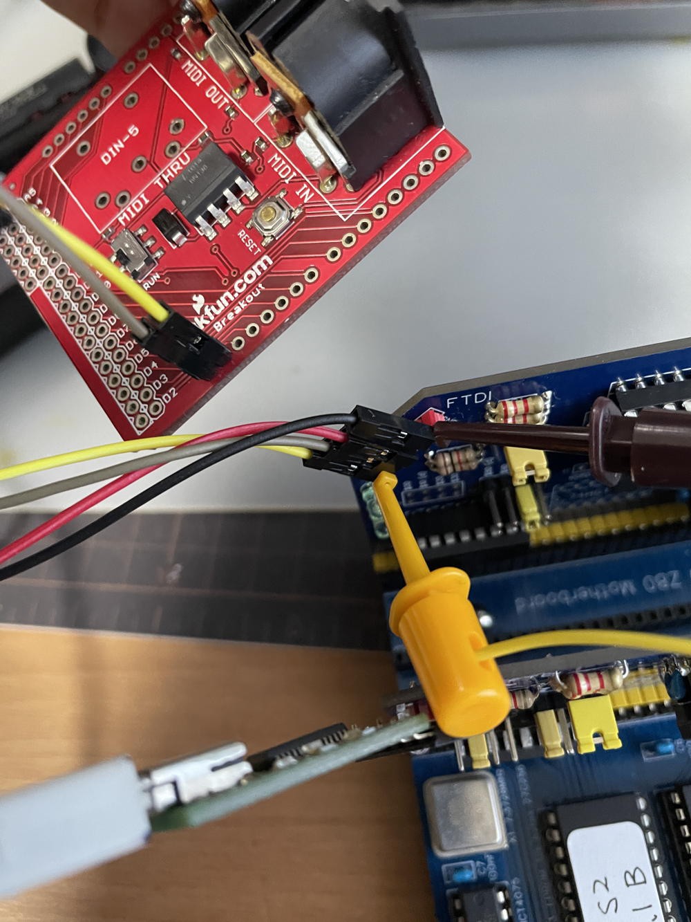
Initially, I intended to use a SparkFun MIDI Shield that I had on hand. However, the shield is designed for Arduino, and its MIDI-OUT circuit connects directly to the pins, making it incompatible with the HD63B50. As a result, I had to design a new MIDI interface with an integrated driver. To keep the design compact, I used a TC7W34 3-channel driver(Triple Non-Inverter) .
TC7W34 is one of my favorite IC, as it is very compact and useful for applications like this. A small SSOP-DIP adapter board makes TC7W34 into 8pin DIP size. For Photo-coupler, I used good old PC910 made by Sharp, which was obsolete long ago.


 morecat_lab
Discussions
Become a Hackaday.io Member
Create an account to leave a comment. Already have an account? Log In.