 DIY GUY Chris
Tools:
- EasyEDA Pro – For PCB design and generating Gerber files.
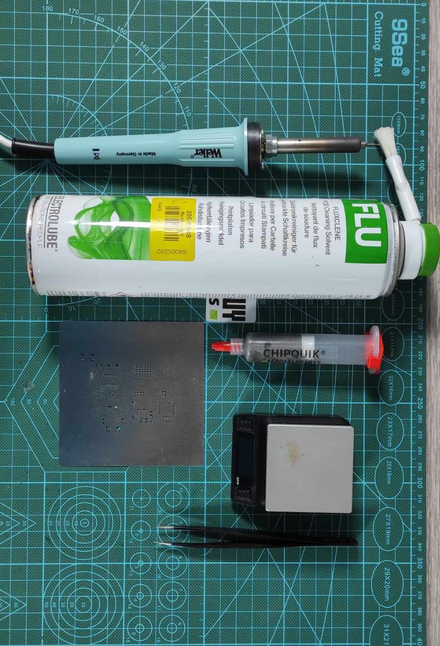
- Soldering Iron – For manual soldering of components. Buy from here
- Miniware Hotplate – For reflow soldering surface-mounted components. Buy from here
- PCB Stencil – For applying solder paste to the board.
- Digital Microscope – For inspecting solder joints and small components. Buy from here
- Flux Remover Solvent – For cleaning the PCB after soldering. Buy from here
- USB Cable – For connecting the custom Arduino board to the computer.
- Multimeter – For testing connections and continuity. Buy from here
- Solder Paste – For applying to surface-mounted components. Buy from here
- Tweezers – For placing small components on the board. Buy from here
These are essential tools to help you replicate my project efficiently!
Designing the Circuit Board
For this project, I designed an Arduino-compatible board that keeps the same form factor as the Arduino Uno but with a unique, personalized color and silkscreen. This gives it a more customized and modern feel, standing out from the usual green PCBs.
Key Components:
- ATmega328 MCU: The heart of the board, just like in the classic Arduino Uno.
- USB-to-UART Converter: For programming the MCU.
- USB-C Programming Port: Modern, fast, and convenient.
- 3x3 RGB LED Matrix: Using WS2812 addressable LEDs for a fun, visual touch. It's connected to pin 9, and I made sure to expose the last data output pixel to make the matrix extendable.
- NE555 Timer: This controls the brightness of a small LED, giving the board a sleek aesthetic.
- Board Dimensions: The board is the same size as the original Arduino Uno. The dimensions can be found in the Arduino hardware reference, making it compatible with existing Arduino shields.
- Headers and Connectors: The header connectors are on the top and bottom sides, and I placed the USB-C programming port and power jack on the front.
Even though I included ISP programming pins, I won’t need them because the ATmega328 MCU already has the Arduino bootloader pre-installed. Read my Instructable about the ISP programming technique
Now, let's move on to the most exciting part: setting the custom color silkscreen for the circuit board.
Using EasyEDA Pro for Color Silkscreen:
- To create this unique design, you’ll need EasyEDA Pro. If you're using another ECAD tool, you can still upload your design files to EasyEDA and apply the color silkscreen.
- First, enable the JLC Color Silkscreen option from the settings menu.

- This allows you to upload an image and use it as the silkscreen on your PCB.

I selected this cover image and resized it to fit perfectly within my board layout.
- For the bottom layer, I added a wallpaper-style design for an extra layer of personalization.
- You can also modify the default component and text silkscreen colors by selecting them and choosing your desired colors from the palette.
![Modify Silkscreen Colors]() Verifying and Generating Gerber Files
Verifying and Generating Gerber Files
 Verifying and Generating Gerber Files
Before moving to production, you can preview the uploaded color silkscreen in both 2D and 3D views to ensure your design is ready.

Once you're happy with the design, generate the Gerber files. Make sure to select the JLCPCB Color Silkscreen option, which will ensure that your colorful design is included in the PCB manufacturing process.

Download GERBER files from here.
Download BOM file from here.
PCB Ordering & Assembly
Now, it’s time to place the order.
- Upload the Gerber files to JLCPCB. Keep in mind, the color silkscreen is available only for 2-layer FR4 boards.
- Select a white solder mask and golden nickel surface finish. These are required to enable the Color Silkscreen feature.
- The ordering process was smooth, and my boards arrived within seven days. The quality was excellent!

Once the boards arrived, I used a stencil to apply solder paste. Here’s how I assembled the board:
1- I placed the components on the board and used my Miniware hotplate to solder them.


2- After soldering, I cleaned the board with some flux removal solvent.

3- Then, I installed the female headers on the sides and soldered them in place. After that, I soldered the male headers on the back and attached the power jack connector.
![Soldering headers and power jack]() Final Test
Final Test
 Final Test
With everything assembled, it was time to test the board!
- I connected the board to my computer using a USB cable and uploaded a simple blinking sketch.
- The onboard user LED blinked as expected, and the NE555 dimming LED worked perfectly with the slide switch.
- The RGB LED matrix also responded beautifully using the LEDFast library sketch.

Conclusion
And that’s it! I’ve successfully created a customized Arduino Uno board with a unique color silkscreen and fun RGB LED matrix. Now, you can too!
This project adds a personal touch to the classic Arduino Uno and allows you to experiment with custom colors and visuals, making it ideal for anyone looking to level up their electronics projects.
Let me know your thoughts in the comments below, and if you enjoyed this tutorial, don’t forget to check out my YouTube channel for more electronics content. Until next time, keep building!