 Michael Mayer
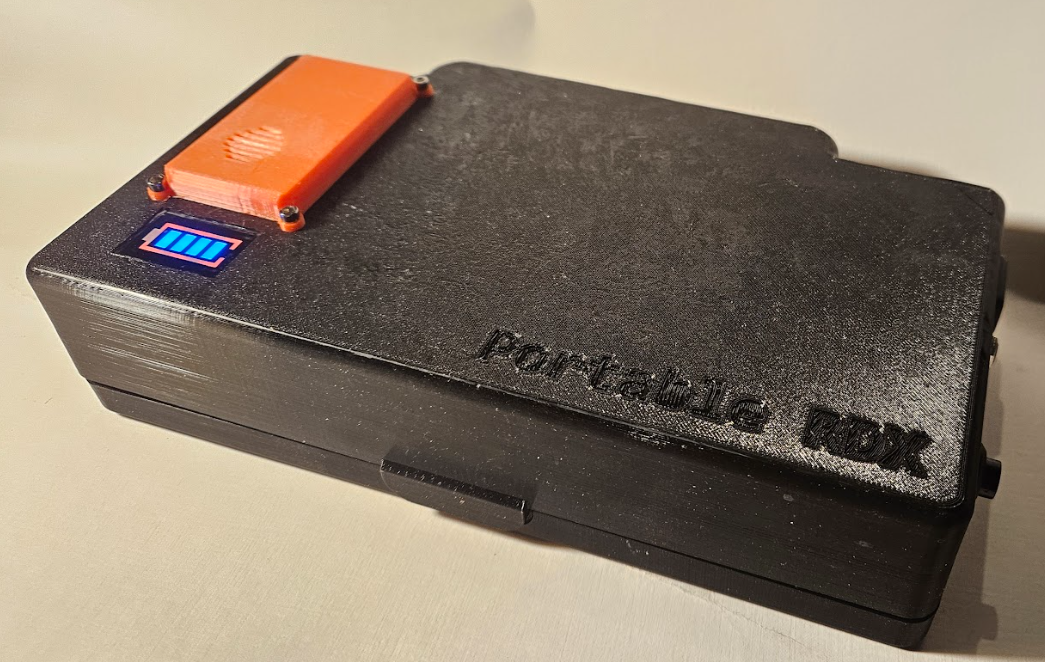
Description
3d Files and Freecad Project can be found under: https://www.printables.com/model/993043-portable-pi-80
Short Video:
NEW: Check out the new Printables Project
https://www.printables.com/model/1088904-portable-pi-rdx
Now Other SBCs are possible, basically all Zero Format SBCs plus the powerful Radxa Zero 2 Pro.
Radxa Zero Pro 3 Expansion:
Expansion Case for any Zero Format SBC.

Remark: All links to amazon are affiliates links.
Audio:
I ordered some TRRS Jacks Male and Female:
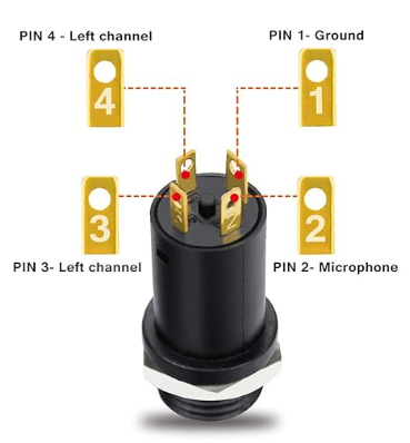
This doesn't mean that microphone will work.
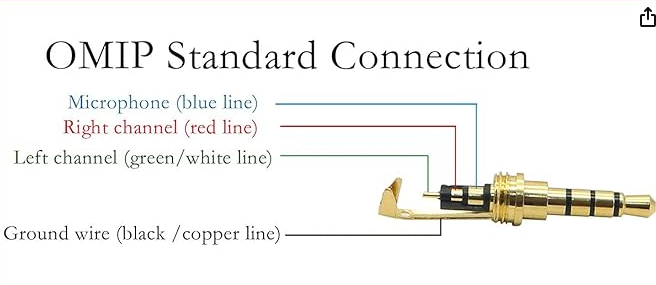
Instead of the above plug you may sacrifice an old headphone cable, but it must be TRRS. (3 Rings)
Plug Detection is working with short of Microphone to Ground. Amplifier for speaker is shutdown then.
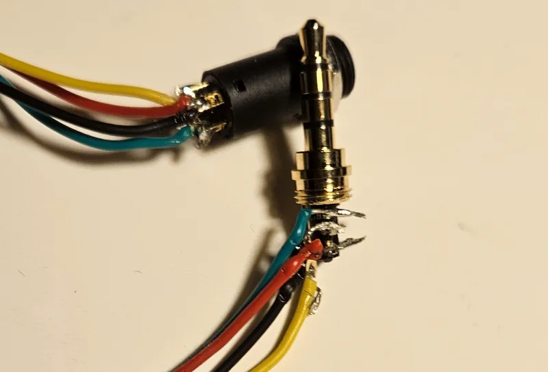
Thanks goes to bootdsc from the Cyberdeck Cafe discord for his help!
Check out his Homepage: https://cyberdeck.cafe/
Example:
Screen:
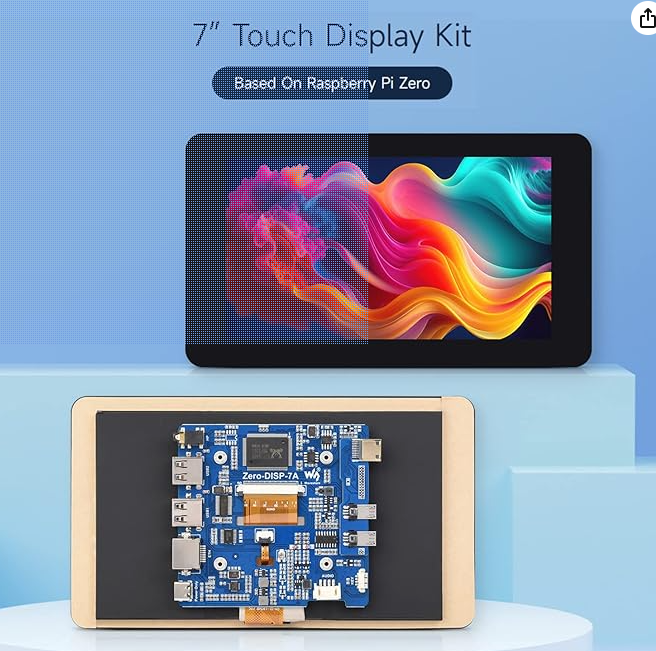
Waveshare Direct: https://www.waveshare.com/zero-disp-7a.htm
Pi Zero 2W:
| EU | US | |
| Amazon Link | https://amzn.to/3XFceRI | https://amzn.to/3BcRcCa |
Printing:
Put the biggest surface on the bottom. Use tree support.
You will need about 350 gram filament.
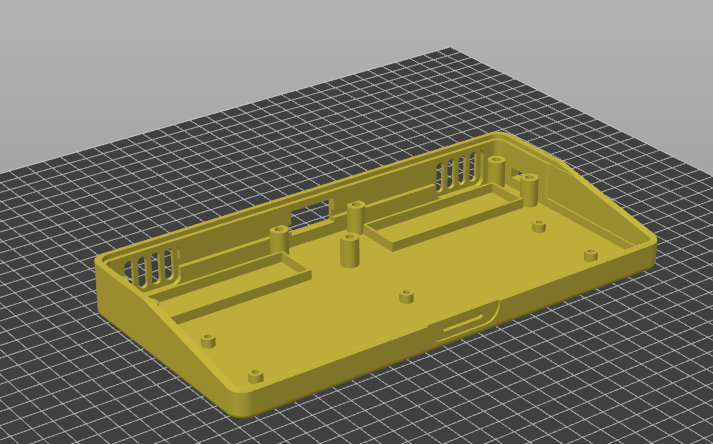
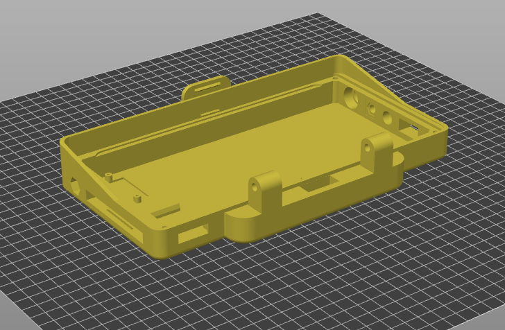
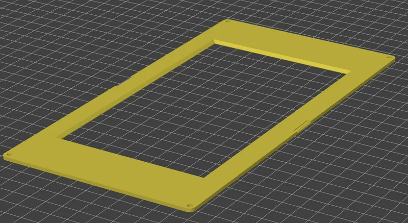
The bevel on the screen cover should be top.
Keyboard:
The keyboard is a Contra 40%. 'You can order it on KEEB (https://keebd.com/products/contra-40-keyboard-kit) or use the github (https://github.com/ai03-2725/Contra) to let it made by a PBC manufactory.
Some quirks with the build process. You have to wire the board and the PBC.
Alternate:
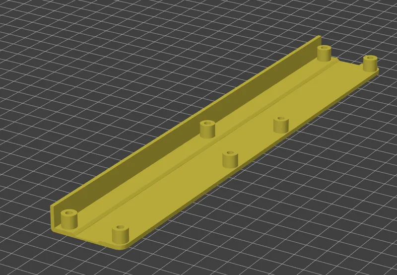
You may also go the route of hand wiring the keyboard. You have the keyboard casket as stl file.
PortablePi80_V17-BOTTOMContraTopPlate 1.stl
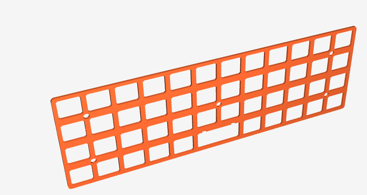
A short description how to do this is on my other project ( portable-pi-84 ) and there are a lot of how-to on the internet.
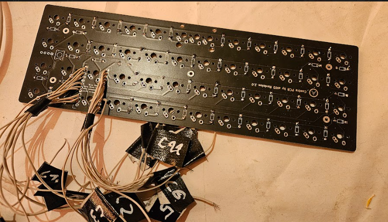
With PCB:
Make the wiring before soldering the switches!
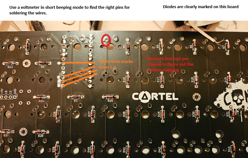
It helped me to solder the wires and lable them with a tape:
Like C1 for column 1 and R2 for Row 2.
Row and Colum Map:

As I soldered it to the nano i marked which wire is soldered to which pin. This is needed for the configuration in KMK.
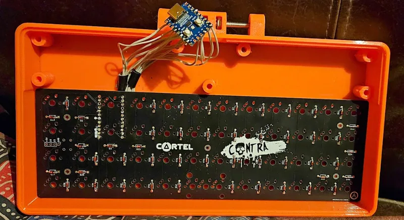
Keep wires in a useful length. It is no place for the nano board underneath the keyboard.
You can place the board in the middle between the 3 screw holes.
For the keyboard software I use Circuit Python with KMK. You need to install Circuit Python and the KMK.
The code.py configuration is included. You may need to take care of the row and column gpio configuration.
# Cols
keyboard.col_pins = (board.GP6, board.GP5, board.GP4, board.GP3, board.GP2, board.GP1, board.GP12, board.GP11, board.GP10, board.GP9, board.GP8, board.GP7)
# Rows
keyboard.row_pins = (board.GP21, board.GP20, board.GP19, board.GP18)
Remark: In seems in the newer version of KMK you may have to change
keyboard.diode_orientation = DiodeOrientation.COL2ROW
keyboard.diode_orientation = DiodeOrientation.ROW2COL
Was for me the case because the keys where not registered but the diodes where all correct.
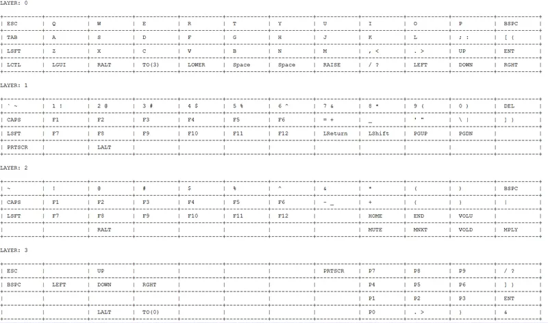
Keymap:
Keyswitches:
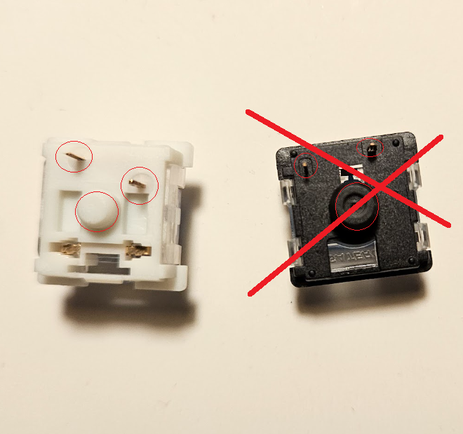
The right Gateron switches will not fit because the center stem is to big and the pins are missaligned. It must be cherry style.
Battery:
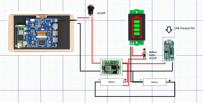
Please be carefully not to short any connection. Check for shorts before insert the Batteries!
Charger must be 2S
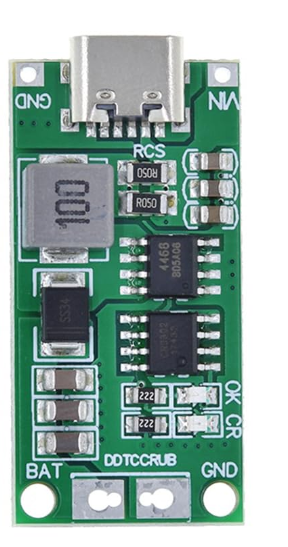

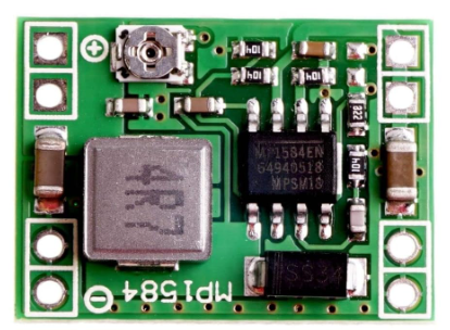
Voltage must be adjusted with Poti on DC-DC Converter to 5 Volt output.
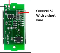
Battery Meter Preparation:
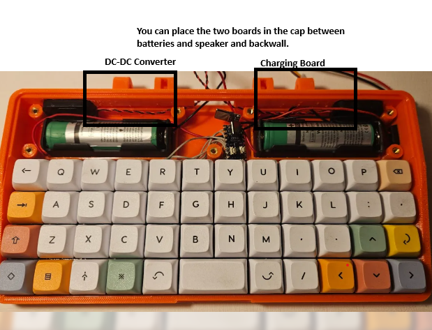
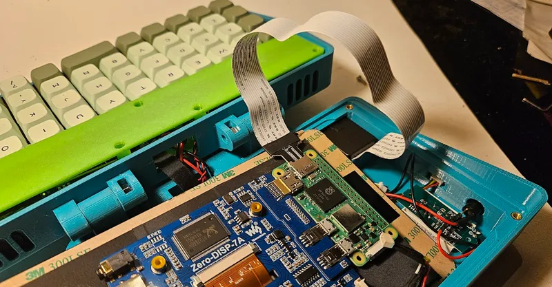
Board Placement:
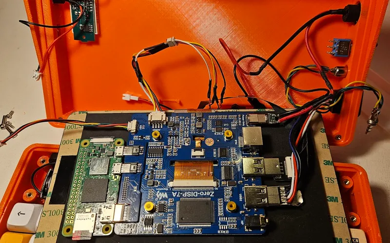
TOP:
Overview: (blue switch on the right is outdated)
Power:
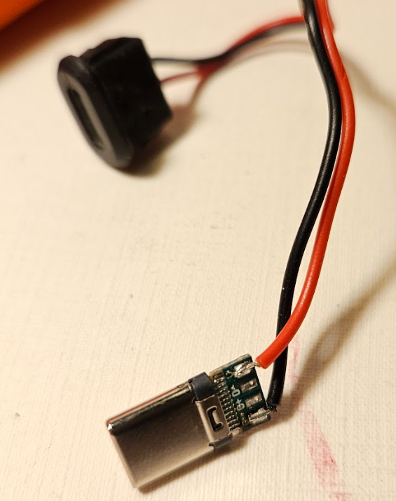
USB-C Connector
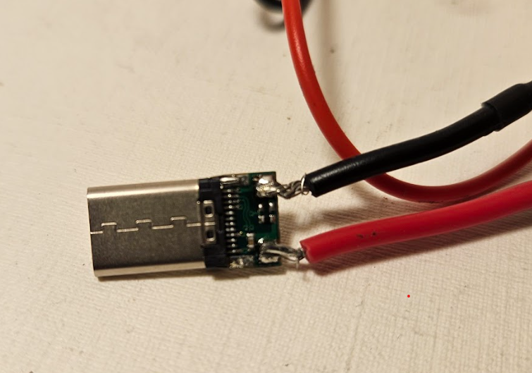
Red to VCC and Black to ground. Please check product page of connector where GND and VCC is. I have two USB-C connector and they are sometimes switched. Don't rely on the image.
Power button is between connector to bottom part positive(red) and USB-C connector(Red)
You can funnel both connectors thought the sidehole.
USB-A Port:
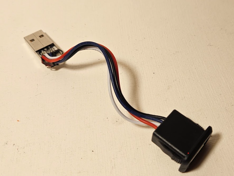
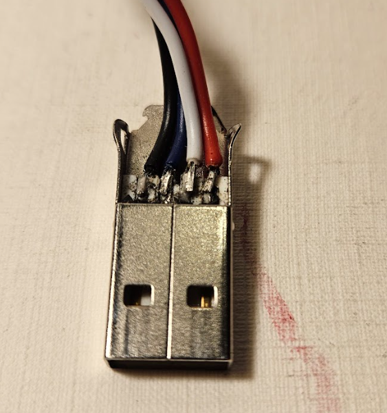
Soldering Black,Blue,White and Red in on to the USB A connector.
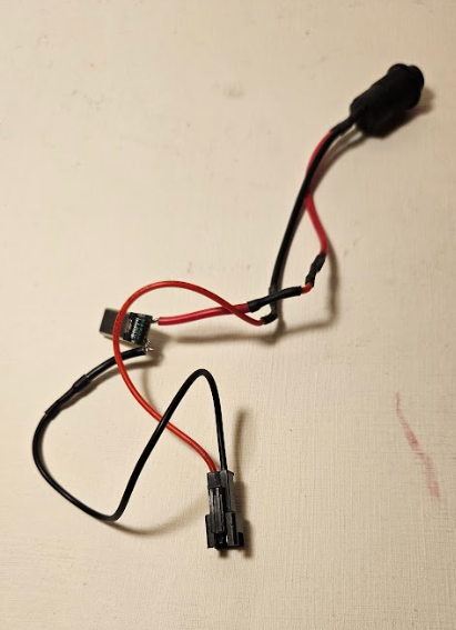
Batterchecker:
Like the powerbutton solder the switch between the red wire. Connect the Battery meter with Red = + and Black = -. The Connector on the bottom is needed for the build.
Audio:
See beginning of the document.
Keyboard USB:
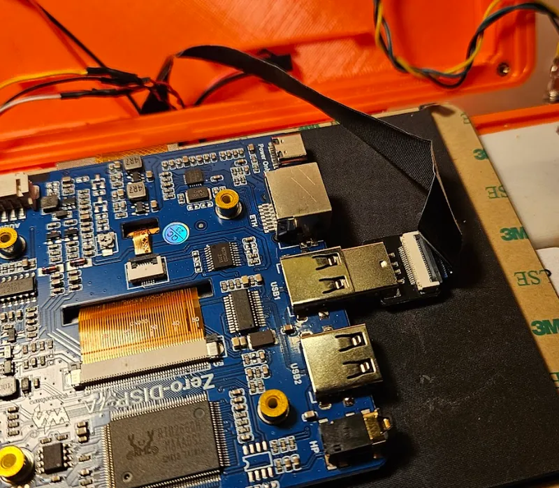
The keyboard is connected with the ribbon cable. You have to remove the USB A pluck to funnel it to the bottom part. When you reconnect remember the black side is always up.
Speaker:
The speaker is simple to connect and funnel from the bottom. The between connector is not necessary.
SD Card Reader:
Put the SD reader in the place left in the bottom of the Toppart.
You have in the other side some negative space to fit the connector to the pi. Put the screen top first in the case.
Bottom:
Overview:
If you have finished the bottom Part it should look like this.:
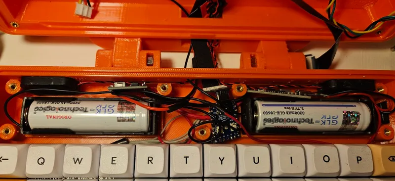
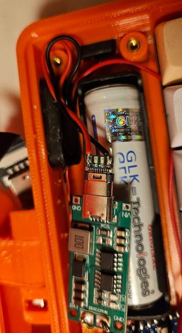
You can see the Speaker and the DC-DC converter (left) and the charging board (right) crammed behind the battery. The gap in the back should help to route the speaker cables.
Keyboard:
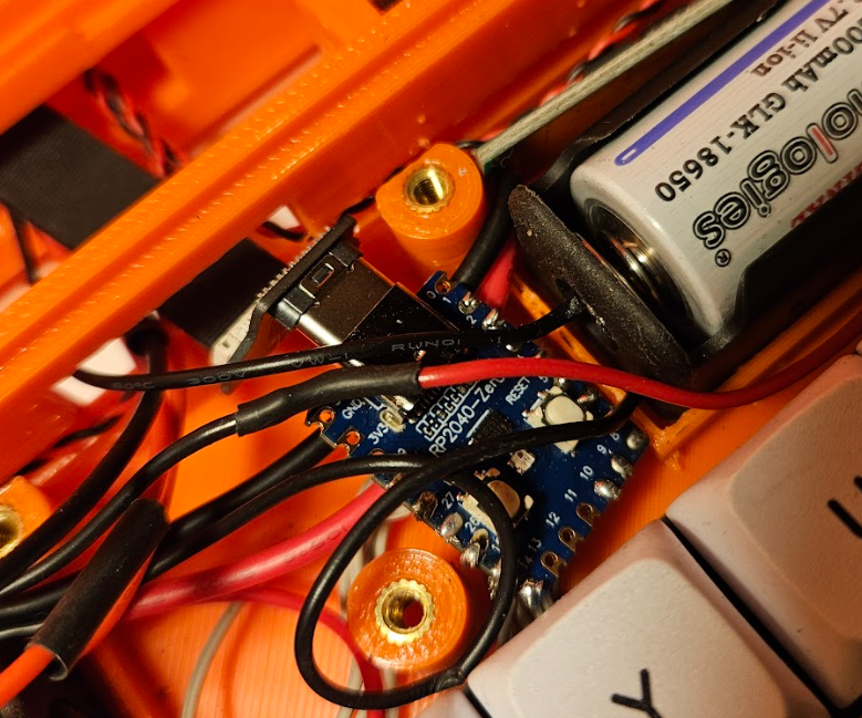
Here can you see how the keyboard nano port is crammed in with the usb-c connector.
Connector:
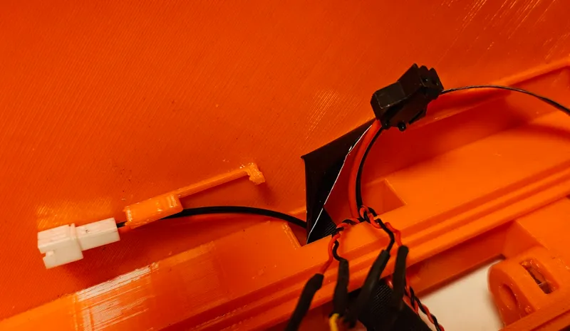
Here you can see the connector for the battery meter(Left) and power (right).
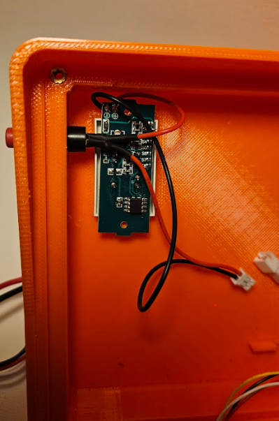
Charging:
The USB-C Connector is connected to the Charging board.
Please check product page of connector where GND and VCC is. I have two USB-C connector and they are sometimes switched. Don't rely on the image.
(Red VC Black GND, You should already know the trill)
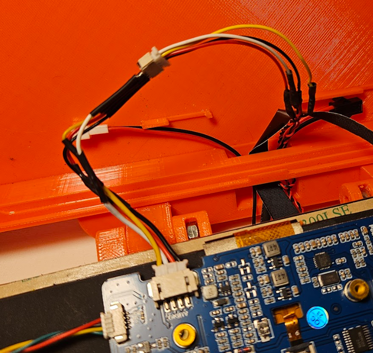
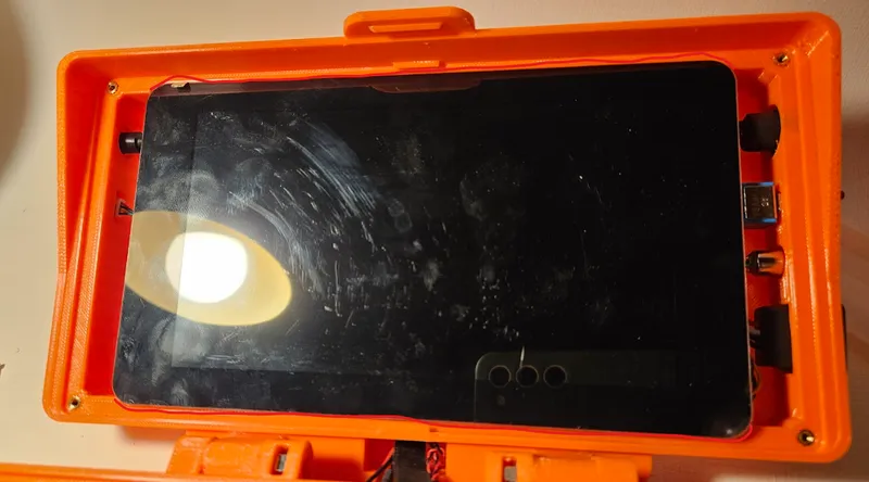
Top Panel:
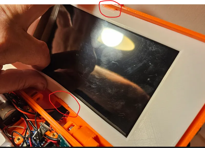
Place the screen into the groove that is present in the top print. Be sure it sits in there, some cables maybe needs to be moved out of way (Ethernet port gets often in the way) You some guides in the bottom to help to organize the cables better. Be Aware that you have to put the SD card reader connector in the top negative space first. When the screen fits fine take the from cover and place it in the top "latch" end bend it horizontally to put it into the bottom groove.
(Be aware, fingerprint alarm!)
Inserts and Screws:
For the Top Front cover you need 3 M Inserts and Screws. (4)
For the Bottom Cover you need 3 M Inserts and Screws (7)
For the Keyboard you need 2 M Inserts and Screws (5)
For the Hinge you need 5 M nut and bolts. (2) The bolts should be 30 mm.
Some final remark:
Please use tube heat shrinks for every connection, no one want to short a battery!
Be careful with you soldering and check every time for shorts before you put in the batteries.
The battery holder is a little annoying so you may snip some of the latched on the top away to easier but the batteries in.
You get a black screen after while, don't worry, this seems to be a sleep mode. You press the space bar and the screen wakes up again. Works fine.
Tools Needed:
Soldering Iron
Solder
Some ribbon cable for the keyboard
Allen keys (they sometimes included with the screw set)
Patience
Partlist:
This are amazon affiliates links.