Close
0%
0%

F.U.F.F. Mux SAO

A Florida-flavored multiplexer for other SAOs

Public Chat
Similar projects worth following

FUFF MUX SAO

The Fast Uplink From Florida is a Florida-flavored multiplexer for Simple Add-Ons, designed especially for Supercon 8.

Description

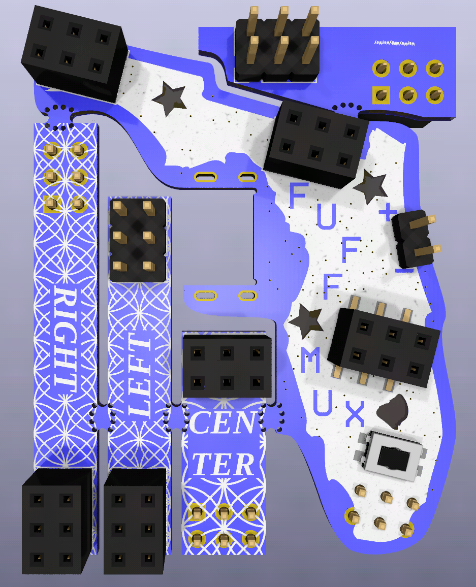
The FUFF MUX SAO provides three fully-featured badge ports for downstream SAOs. In order to accomodate full-sized SAOs, it provides break-away extensions to create additional space so that SAOs don't overlap or collide.

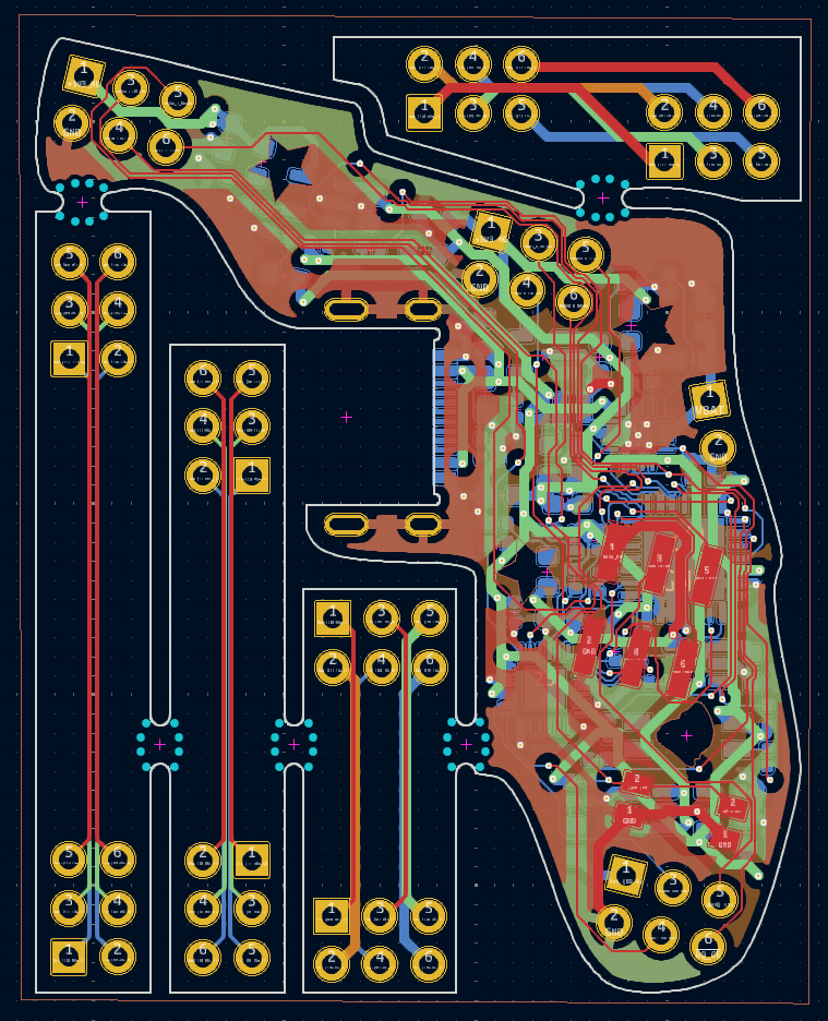
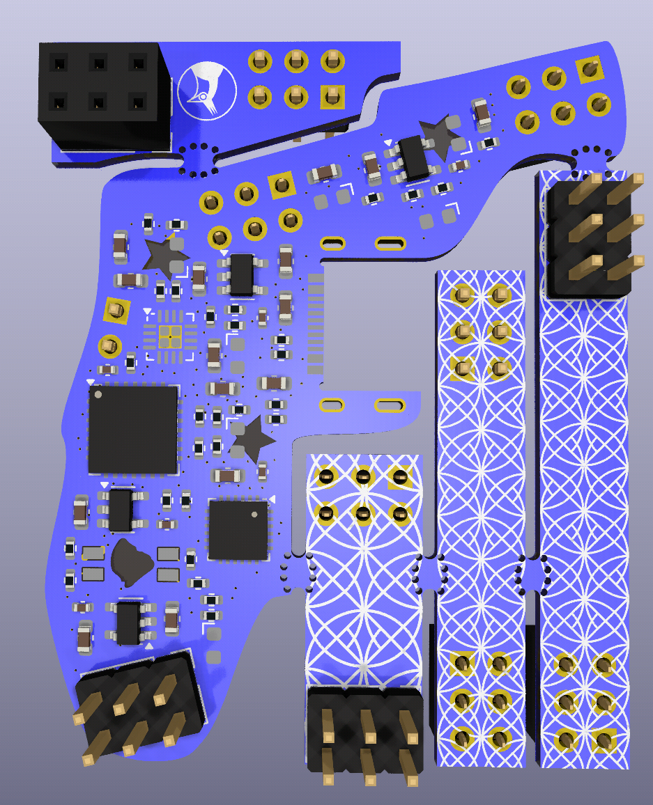
The board contains the following components:

  • TCA9548 I2C multiplexer to give each badge it's own dedicated I2C bus so there is no need to worry about address conflicts!
  • MCP23017 I/O expander to handle the GPIO from attached SAOs. It is attached to the TCA9548 (as opposed to the main downstream I2C bus) to minimize the addresses presented to the badge downstream.
  • BQ24074 charger and dedicated battery. Since the SAO spec only guarantees approximately 250mA @ 3.3V in the power budget, the FUFF mux needs to be able to provide its own power - 750 mA for downstream devices plus whatever it uses for itself
  • USB-C (the One True Port) and controllable 3.3V regulators. Turn off annoying blinking lights on other SAOs programmatically or power cycle them if they misbehave
  • A user button connected to the GPIO expander. It can be used for anything, but demo code will allow it to be used to power cycle the attached devices according to some pattern
  • RGB LED backlight for Lake Okeechobee connected to the GPIO expander

The FUFF MUX can even be daisy-chained to support a literally infinite number of SAOs, compared to something like IPv6 which can only support 2^128 unique addresses.
Unfortunately, with a chain of 340 undecillion (2^128) FUFF MUXes, round trip message latency at 400kbps is expected to be about 512.5 yotta-years, at which point humanity may no longer exist.

Repo Structure

  • fuff-sao-pcb/ - Kicad project containing hardware files
  • fuff-sao-fw/ - Micropython firmware providing drivers and example code
  • assets/ - Images, docs, etc. for linking against in the README

Setup

TODO

License

Solderpad V2.1 Hardware License

  • 15 × Capacitor - 10uF - 10V - Ceramic - X7R - 0603 Passive Filters / Crystal
  • 6 × Capacitor - 100nF - 10V - Ceramic - X7R - 0402
  • 7 × APA1606SURCK LEDs and Accessories / Light Emitting Diodes (LEDs)
  • 1 × XZMDKCBDDG45S-9 LEDs and Accessories / Light Emitting Diodes (LEDs)
  • 1 × Molex 2169900003

View all 19 components

  • Supercon 8, Baby!

    Patrick Lloyd11/03/2024 at 19:44 0 comments

    The FUFF MUX is real and in the flesh (kinda)! I asked PCBWay to express ship the boards to Pasadena and they made it just in time for the con. I also got a bunch of parts in from Digikey and got to work putting together the first one on Friday during the badge-hacking and party on Friday.

    I spent some time on Saturday finishing up the first one (removing shorts and whatnot) but before I could make any more, the hot plate managed to melt its own temp controller and died lol

    I went to LACM after to enjoy some talks and continued FUFFin away. Now to see where we get to on sunday.

    Pics incoming. I was having some technical difficulties getting them uploaded.

  • Update [Oct 14, 12:51 PM PDT] - Fabulous Fabrication (Redux)

    Patrick Lloyd10/15/2024 at 05:17 0 comments

    Board files have been successfully submitted to PCBWay for approval and fabrication. With the demo code working and the design off to manufacturing, I'm satisfied that I have done everything I can to meet the minimum requirements for contest qualification. Still, there are many things to do in preparation for the boards arriving:

    • Clean up the Git repo and upload the design files there and here
    • Order the parts (now that they're all available for purchase)
    • Work on the docs
    • Make a few "set-and-forget" example programs (based on the existing demo code) in MicroPython, CircuitPython, and Arduino C++
    • Make a video on the FUFF MUX
    • Create an item on Tindie 

    These are all good stretch goals for Supercon. Even if the FUFF MUX doesn't win the contest, it'll still be for sale :]

  • Update [Oct 12, 11:48 PM PDT] - The (breadboard) FUFF MUX Lives!!!

    Patrick Lloyd10/15/2024 at 03:25 0 comments

    The FUFF MUX works as designed. I breadboarded each of the ICs included on the PCB, as well as three different I2C devices I had in my parts box:

    • FUFF MUX
      • 3.3V regulators (the breadboard used the D36V6F3 instead of the SPX3819M5-L-3-3)
      • BQ24074 - Battery charger
      • MCP23017 - GPIO expander
      • TCA9548A - I2C multiplexer
    • External Devices
      • MCP9808 - temperature sensor
      • MPU9250 - combined 3-Axis gyroscope / 3-Axis accelerometer with a separate AK8963 3-Axis magnetometer on the same die
      • VL53L0X - ToF lidar sensor
      • RP2040-Tiny - main controller for I2C devices

    Here are some fun pics of the breadboard in all its messy glory:


    This is the `main.py` file I wrote, but the Git commit with library submodules is coming soon.

    from machine import UART, Pin, I2C, Timer
    from micropython_mcp9808 import mcp9808
    from mpu9250 import MPU9250
    from ak8963 import AK8963
    import VL53L0X
    import mcp23017
    import tca9548a
    import time, utime
    
    '''
    TODO:
    Yaks to shave:
    - [x] Proof of life from Pico by enumerating U2F drive on laptop and accepting a compiled program
    - [x] Serial communication - UART0 is Bogarted by Thonny so we have to use UART1 for traditional USB-serial comms
    - [x] I2C hello world - do a scan and see at least one device at the expected address
    - [x] I2C Read and write MCP9808 temp sensor (at least individually)
    - [x] I2C Read and write MPU9250 IMU sensor (at least individually)
    - [x] I2C Read and write VL53L0X ToF sensor (at least individually). Don't forget to remove the P&P Kapton
    
    Meat & Potatoes
    - [x] I2C Read and write TCA9548A I2C Mux (at least individually)
    - [x] I2C Read and write MCP23017 GPIO expander (at least individually). Consider switches 
    - [x] I2C read & write through multiplexer
    
    '''
    
    uart1 = UART(1, baudrate = 115200, tx = Pin(4), rx = Pin(5))
    i2c0 = I2C(0, scl = Pin(1), sda = Pin(0), freq = 100000)
    i2cmux = tca9548a.TCA9548A(i2c0)
    
    def test_ext_uart_mon():
        print("test_ext_uart_mon: Testing UART transmission to external serial monitor...")
        
        txData = b'hello UART, from RP2040!\n\r'
        uart1.write(txData)
        print(txData)
        
        print("test_ext_uart_mon Complete")
        print()
    
    def test_i2c_scan_chain():
        print("test_i2c_scan_chain: Testing I2C read capabilities:")
        
        print("Devices on I2C0: ")
        print(" ".join(hex(n) for n in i2c0.scan()))
        
        print("test_i2c_scan_chain Complete")
        print()
    
    def test_temp_sensor():
        print("test_temp_sensor: Testing MCP9808 temperature sensor writing and reading")
    
        temp = mcp9808.MCP9808(i2c = i2c0, address = 0x18)
        
        for tempres in mcp9808.temperature_resolution_values:
            print(f"Writing temperature resolution setting: {tempres}")
            temp.temperature_resolution = tempres
            print("Reading temperature resolution setting: ", temp.temperature_resolution)
            for sample in range(10):
                print(f"Reading temperature {sample+1}/10: {temp.temperature:.4f}°C")
                time.sleep(0.2)
                       
            print("test_temp_sensor Complete")
            print()
    
    def test_imu():
        print("test_imu: Testing MPU9250 IMU writing and reading")
        
        dummy = MPU9250(i2c = i2c0)
    
        print(f"Reading MPU9250 id: {hex(dummy.whoami)}")
        print(f"Writing calibration info for magnetometer")
        
        ak8963 = AK8963(
            i2c0,
            offset=(-136.8931640625, -160.482421875, 59.02880859375),
            scale=(1.18437220840483, 0.923895823933424, 0.931707933618979)
        )
        
        imu = MPU9250(i2c = i2c0, ak8963 = ak8963)
        
        for sample in range(10):
            print(f"Reading MPU9250 Sensors {sample+1}/10")
            print(f"Accel: {imu.acceleration}")
            print(f"Gyro:  {imu.gyro}")
            print(f"Mag:   {imu.magnetic}")
            print(f"Temp: {imu.temperature}")
            time.sleep(0.1)
            
        print("test_imu Complete")
        print()
    
    def test_tof():
        print("test_tof: Testing VL53L0X ToF Lidar writing and reading")
        
        tof = VL53L0X.VL53L0X(i2c0)
        
        print(f"Writing pulse period info for ToF")
        tof.set_Vcsel_pulse_period(tof.vcsel_period_type[0], 18)
        tof.set_Vcsel_pulse_period(tof.vcsel_period_type[1], 14)
        
        tof.start()
        tof.read()
        for sample in range(10):
            print(f"Reading ToF Sensor {sample+1}/10: {tof.read()}")
            time.sleep(0.1)
            
        tof.stop()
    
        print("test_tof Complete")
        print()
    
    def...
    Read more »

  • Update [Oct 8, 8:32 PM PDT] - OH NO I FUFF'D UP!

    Patrick Lloyd10/15/2024 at 02:30 0 comments

    After submitting the board to PCBWay for fab, I realized I made a really dumb mistake. In order to move quickly (and recklessly), I selected an I2C GPIO expander IC with a small footprint: the STMPE1600. I designed the whole damn board before trying to put together the BoM and discovered that this expander is complete and utter unobtanium. It's an obsolete part that has been discontinued by the manufacturer and can't be ordered through the normal channels in any sort of reasonable time frame. 

    The only reasonable choice I have (and what I should have done at the beginning) was to select a GPIO expander with less supply chain risk. I've decided on the MCP23017 which has a lot of available stock on Digikey, breakout boards, and community support. but the smallest package size is 0.6mm x 0.6mm larger and has a completely different pinout than the STMPE1600.

    This requires a significant rework of the board design at a time when I don't have much time to spare! Since the lead time for the PCB is going to be 8-9 days anyway (after the contest deadline), I'm going to pivot to a new strategy that hopefully still meets the submission requirements. I have breakout boards for each IC on the FUFF MUX and will create a breadboard so that I can begin writing software to prove out the functionality of the design ("works like the final design; doesn't look like the final design"). I hope that with the software taken care of  and the board redesigned and sent to fab by the deadline, this will acceptably be considered a "working prototype" per the contest rules.

  • Update [Oct 7, 12:47 AM PDT] - The FUFF MUX SAO has a PCB sponsor!

    Patrick Lloyd10/15/2024 at 01:32 0 comments

    Today, Liam from PCBWay reached out to me over the Hackaday.io DMs and offered to have PCBWay sponsor the prototype fab run of the FUFF MUX!  I'm very excited about this partnership. I've seen some of the amazing projects that PCBWay has been a part of, as well as some of the cool (and informative) videos they've posted over the years.

    I'm still polishing up the PCB design (making silkscreen pretty, squashing some last-minute DRC issues, etc.) but stay tuned for more info as we move toward a sick-awesome custom FUFF MUX board.

  • Git Commit [Oct 5, 2024, 1:02 AM PDT] - Finished routing more or less. Needs some clean up aesthetically.

    Patrick Lloyd10/15/2024 at 00:24 0 comments

    Link to Commit on Codeberg

    Progressssssss! Dumping all the files and will clean up later. Looking into different board manufacturers.

  • Git Commit [Sep 12, 2024, 12:33 AM PDT] - Finished schematic enough for a review. Generated PDFs for distribution.

    Patrick Lloyd10/15/2024 at 00:10 0 comments

    Link to Commit on Codeberg

    The schematic is done! Also had to invert the soldermask on the SVG - any objects on the *.Mask layers tell Kicad where to REMOVE solder mask material. This is in contrast to the *.Silk layers where any items on it tell Kicad where to ADD silkscreen ink.

  • Git Commit [Sep 11, 2024, 11:52 AM PDT] - Trivial changes to test RSS feed in element

    Patrick Lloyd10/14/2024 at 23:50 0 comments

    Link to Commit on Codeberg

    Very minor update. Since the main chat for this project is  on Matrix, I wanted to add updates to the room using the RSS feed provided by Codeberg. This commit tests the Feed Bot

  • Git Commit [Sep 11, 2024, 11:46 AM PDT] - Added more connections to the top sheet w/ hierarchical pins, added more notes to clarify how project is organized, cleaned up the project to reduce some visual clutter

    Patrick Lloyd10/14/2024 at 23:37 0 comments

    Link to Commit on Codeberg

    Just a checkpoint update to help clear up some messy schems

  • Git Commit [Sep 10, 2024, 10:42 PM PDT] - Removed spurious Gingerbread files, added per-layer exports from Inkscape, and added the completed mux section to the schem

    Patrick Lloyd10/14/2024 at 23:26 0 comments

    Link to Commit on Codeberg

    I learned that Kicad can import SVG's directly and there's no need for Gingerbread. Additionally, Gingerbread has an open issue where it specifically does not support Inkscape. 

    Per-layer exports from Inkscape refer to the creation of specific PCB-centric layers like F.Cu, B.Mask, etc. rather than logical layers like "fit check" and "useful shapes".

View all 15 project logs

Enjoy this project?

Share

Discussions

Similar Projects

Does this project spark your interest?

Become a member to follow this project and never miss any updates