Close
0%
0%

Hack-Man SAO

A Pac-Man themed SAO using an obscure but cheap microcontroller

Similar projects worth following
Hack-Man is a Pac-Man themed SAO with a number of operation modes.

Its default mode emulates the state of the actors in the Arcade version of Pac-Man during its attract-mode.

A button switches through the additional modes which are:

  • Slow hue cycle
  • Discrete Larson scanner that slowly changes hue
  • Slower Larson scanner that retains the correct actor colors with a slow fade.

If the SAO detects valid I2C commands to its address (0x1A), it will switch to I2C command mode and fall back to regular mode if there are no valid I2C commands for a while.

I2C commands are always 4 bytes long and currently supports the following:

  • [0-5 Led Index 0=rightmost] [0-255 Red][0-255 Green][0-255 Blue] - Cues an LED color
  • [5] [x][x][x]- Clear all colors
  • [6][x][x][x] - Latch the colors
  • [7][0-255 Brighness][x][x] - Set global brightness, 0=off, 255 = max
  • [128-132 Led index-128] [0-255 Red][0-255 Green][0-255 Blue] - Cues an LED color ignoring global brightness

At bootup, the SAO lights all the LEDs in their appropriate colors for 1 second, then flashes the major (white) and minor (green) revision numbers in binary for 1/2 second each before switching to the default mode (this is mainly to help me validate the assembly and know which SAOs are flashed to the latest code)

Demo of I2C mode, being driven from my Polar Pac-Man game on last year's Vectorscope badge

Arcade attract mode (default mode), compared to the actual arcade machine.

Other modes

Screenshot 2024-10-06 202032.png

ARM Keil uVision IDE

Portable Network Graphics (PNG) - 248.75 kB - 10/07/2024 at 03:21

Preview

image(1).png

PY32F002AL Pinout

Portable Network Graphics (PNG) - 19.88 kB - 10/06/2024 at 17:27

Preview

Screenshot 2024-08-21 093611.png

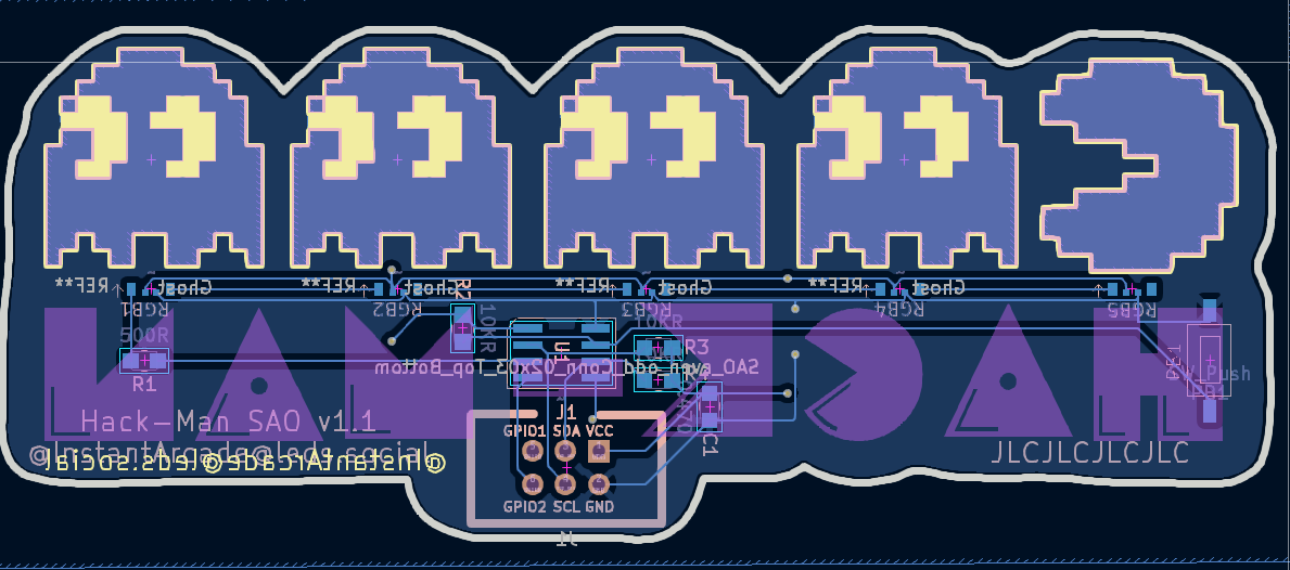
3D Render from KiCAD

Portable Network Graphics (PNG) - 54.04 kB - 10/06/2024 at 17:27

Preview

image.png

Design in Inkscape

Portable Network Graphics (PNG) - 96.42 kB - 10/06/2024 at 17:25

Preview

  • 1 × Puya PY32F002A An $0.10 ARM Cortext M0+ compatible SOP-8 microcontroller
  • 5 × SK6805-EC3210R SMD-4P,1.48x3.2mm RGB LED
  • 1 × 500R 0805 SMD Resistor
  • 1 × 6.3V .47uF X5R ±20% 0805 Multilayer Ceramic Capacitor
  • 1 × 3.5mm 2.5mm Rectangle button

View all 6 components

  • The illusion of diffusion

    InstantArcade (Bob)10/08/2024 at 22:58 2 comments

    Since the SK6805 RGB LEDs are side-firing, they don't emit much light through the PCB, leaving a lackluster showing.

    My first attempt at diffusion was to laser-cut some clear acrylic in the outlines of the shapes to act as a kind of light pipe in the hope that helped. The result was barely imperceptible.

    I roughed up the back of the acrylic in the hope that would bounce more light through the front, but the majority of the light still was strongest at the edges.

    Next I tried 3D printing a frame and adding reflective material to the back to help bounce the light through. This worked okay, but logistically it's a bunch of extra fiddly work and I still hadn't come up with a good way of fixing it to the PCB.

    Finally I tried some hot glue, and it made the biggest difference for the least amount of work. It's a bit messy, but it works, and it's on the back where no-one is looking :)

  • Reverse Indexing

    InstantArcade (Bob)10/08/2024 at 22:24 0 comments

    Due to the pinout/footprint of the SK6805 RGB LEDs, it was more beneficial to arrange them so that the final ghost was LED 0, and Pac-Man was LED 4. This way I was able to connect DOUT to the next LED's DIN with a direct line.

    This ended up being a tradeoff between software gymnastics to mirror the indexes, or having a far more difficult to route PCB layout, particularly with all of that empty space where I can't have copper or soldermask because I want only the FR4 exposed to allow the light through from the back.


    Just remembering to mirror the indexes proved pretty straightforward and in some case you can use easier helpers e.g.

    #define PAC_MAN_LED_INDEX 4

  • Perfecting the pinout

    InstantArcade (Bob)10/07/2024 at 04:44 0 comments

    Now, here's the challenge:

    The micro has only 8 pins, and the SAO connector has 6 and there are limitations to the configuration of the pins, and the functions they support, so the right choices here are critical.

    I need the following:

    • VCC & GND
    • A regular GPIO for pushbutton input
    • SDA and SDC for I2C input
    • SPI MOSI to drive the RGB LEDs
    • Retain the SWDIO and SWCLK for programming/debugging.

    This took equal parts planning and experimentation, with one layout revision and re-routing the board, but I was able to make it work. The key to this success was changing Pin 6 NRST function to a regular GPIO, and this is achieved by setting some user options in the flash. Again, I relied on a HAL example to get this to work, and the SAO will check the mode on boot up and set the flash if it needs to then reboot - this is completely reversible by changing a define in the code and recompiling, so I didn't brick any of my $0.12 chips :)

    This is the magic bit of code that makes it possible and the first thing that happens in the main() function.

      HAL_Init();
    
      /* Check RST pin mode */
    #if defined(RSTPIN_MODE_GPIO)
      if( READ_BIT(FLASH->OPTR, FLASH_OPTR_NRST_MODE) == OB_RESET_MODE_RESET)
    #else
      if( READ_BIT(FLASH->OPTR, FLASH_OPTR_NRST_MODE) == OB_RESET_MODE_GPIO)
    #endif
      {
    		// program option byte
    		HAL_FLASH_Unlock();        /* Unlock FLASH */
    		HAL_FLASH_OB_Unlock();     /* Unlock OPTION */
    
    		FLASH_OBProgramInitTypeDef OBInitCfg = {0};
    
    		/* Configure OPTION settings */
    		OBInitCfg.OptionType = OPTIONBYTE_USER;
    		OBInitCfg.USERType = OB_USER_BOR_EN | OB_USER_BOR_LEV | OB_USER_IWDG_SW | OB_USER_NRST_MODE | OB_USER_nBOOT1;
    
    	#if defined(RSTPIN_MODE_GPIO)
    		/* Disable BOR/Enable BOR rising 3.2V, falling 3.1V/Software watchdog mode/GPIO functionality/System memory as boot area */
    		OBInitCfg.USERConfig = OB_BOR_DISABLE | OB_BOR_LEVEL_3p1_3p2 | OB_IWDG_SW | OB_RESET_MODE_GPIO | OB_BOOT1_SYSTEM;
    	#else
    		/* Disable BOR/Enable BOR rising 3.2V, falling 3.1V/Software watchdog mode/RST functionality/System memory as boot area */
    		OBInitCfg.USERConfig = OB_BOR_DISABLE | OB_BOR_LEVEL_3p1_3p2 | OB_IWDG_SW | OB_RESET_MODE_RESET | OB_BOOT1_SYSTEM;
    	#endif
    
    		/* Start option byte programming */
    		HAL_FLASH_OBProgram(&OBInitCfg);
    
    		HAL_FLASH_Lock();      /* Lock FLASH */
    		HAL_FLASH_OB_Lock();   /* Lock OPTION */
    
    		/* Generate a reset to load the option bytes */
    		HAL_FLASH_OB_Launch();
    	}	
    

    This means I can then go on to use Pin 6 (PA2) in it's alternate function mode as I2C SDA.

    The final pin configuration I used is as follows.

    Pin Name
    FunctionSAO Header
    1
    Vcc
    Power in
    VCC
    2PA4/PA10I2C SCL (alternate function)
    SCL
    3PA3SPI MOSI (LED driver)
    N/A
    4PA14-SWC/PB3SWCLK (for programming/debugging)
    GPIO2
    5PA13-SWDSWDIO
    GPIO1
    6PA2/PF2I2C SDA
    SDA
    7PA1GPIO pushbutton input
    N/A
    8VssGroundGND

    This configuration theoretically means you could make a SWD compatiple programmer from your badge and re-program the SAO from it.

  • Low-level vs Hardware Absraction Layer

    InstantArcade (Bob)10/07/2024 at 03:19 0 comments

    The next struggle I faced was getting certain things to work while poking at the hardware directly using the low-level registers.

    I studied the comprehensive datasheet and reference manual thinking I had a good handle on everything. While GPIO seemed to work just as expected, I had issues with getting I2C working properly, and also could not get flash working either.

    I had avoided the Hardware Abstraction Layers (HAL Drivers) thus far, fearing the bloated flexibility would eat up my precious memory and not leave enough for what I wanted.

    After many days of struggle, I tried a few HAL examples, and was surprised that they worked just as intended, so I ended up copying the HAL sample projects and retrofitting my code into the example's shell.

    Bottom line is that using the HAL saves a bunch of time and frustration, and is also more intuitive to program, e.g.

    The low-level way to set up GPIO

      GPIOA->MODER = (GPIOA->MODER  & ~((uint32_t)0b11<<(1<<1)));
      GPIOA->PUPDR = (GPIOA->PUPDR & ~((uint32_t)0b11<<(1<<1)))
                    | ((uint32_t)0b01<<(1<<1));
    

    The HAL way  (more verbose, but much nicer)

    	GPIO_InitTypeDef GPIO_InitStruct;
    	GPIO_InitStruct.Pin = GPIO_PIN_1; 
    	GPIO_InitStruct.Mode = GPIO_MODE_INPUT;
    	GPIO_InitStruct.Pull = GPIO_PULLUP;
    	GPIO_InitStruct.Speed = GPIO_SPEED_FREQ_HIGH;
    	HAL_GPIO_Init(GPIOA, &GPIO_InitStruct);
    

    The HAL helpers and defines are much easier to work with and make your code far more readable so you can ignore the complexities of the hardware quirks and focus on the more meaningful magic of your project.


    For the curious, you can step through the HAL code in the debugger and see what it's doing at the hardware level. I was surprised to see that it didn't always follow the datasheet 1:1 which some unexplainable bit setting here and there. At least I don't need to worry too much about it now.

    Another thing I found out far too late - Since this chip is based on an ARM Cortex M0+ (possibly not licensed though), you can search from problems using "STM32" or "Core M0+" when you get stuck on things and the solutions may actually work, or at least get you closer to the answer.

  • Getting Set up

    InstantArcade (Bob)10/07/2024 at 03:01 0 comments

    The Puya PY32F002A at the time of writing is not as widely supported as many other micro-controllers, but it is really cheap - ~$0.12 each when you buy 100 qty.

    Getting a dev environment up was a challenge and it took a frustrating amount of time to find something workable, with many missteps along the way.

    What I ultimately landed on (and recommend), is using ARM's Keil MDK with uVision which can be downloaded for just the cost of your email here.

    Once you have that, get the latest Puya firmware from their website. At the time of writing, that's version 1.41 and can be found here.

    The SDK includes several projects that are already set up for uVision, and I recommend using them as a starting point.

    The last thing you'll need is a programmer - You can't (easily) program the PY32F002A over UART like you're used to, so you need a programmer compatible with ARM's Serial Wire Debug (SWD) protocol. I ended up with 3 different programmers, but to be honest on of the cheap ST-Link v2 clones works just fine. The bonus for jumping through this particular hoop is that you will have breakpoints and step by step debugging - absolute luxury!

View all 5 project logs

Enjoy this project?

Share

Discussions

Similar Projects

Does this project spark your interest?

Become a member to follow this project and never miss any updates