This project is a bit out of my wheelhouse. I recently attended the Rocky Mountain Woodturners Symposium, in Loveland, CO, USA. One of the demonstrators was showing how to create items that appeared to be baskets even though they are made of wood. I had already spent a small fortune on beading tools for the wood lathe and did not want to invest any more into the project. The wood burner that the demonstrator recommended was made by Razortip (>$130 for the power source), or Prescribed Burn II ($650 for a burner and micro-motor carver).
Besides, I convinced myself that it couldn't be that difficult to just heat up a piece of wire. But the trick is to just heat up a single short piece of wire and not all of the other wires involved. I bought a length of 18AWG (1mm diameter) 80/20 nichrome wire to use for experiments and also to make tips going forward. After reading about nichrome wire and performing a couple simple experiments I determined that the wood burner will need to generate between 10A and 15A of current through the nichrome tip in order to heat the tip between 400C and 1000C.
Others Have Tried and Succeeded:
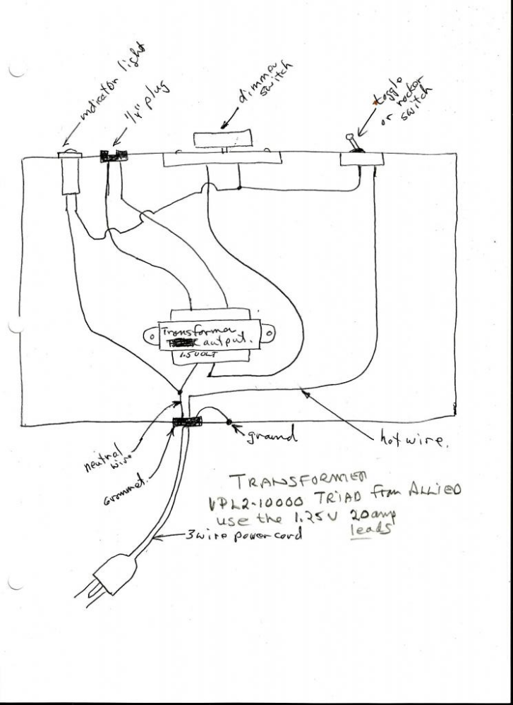
I did not check the internet for evidence that this problem had been solved previously. It has. If you Google "Pyrograph Schematic" it returns a bunch of stuff, with a relatively few relevant sites or nonexistent webpages. But here's a good alternative:

This is pretty straightforward -- a power transformer connected to either 120VAC or 240VAC with a secondary output of either 1.25VAC/20A or 2.5VAC/10A, depending upon how it is connected. It even sports a power indicator! The author recommends connecting it for 1.25V/20A. A look at the data sheet shows that the input/output is specified as 115V/1.25V. If 125VAC is applied to the primary then you can expect the secondary to output 1.359VAC. This will apply a bit over 12A to 20AWG (80mR) nichrome wire tip (along with the leads to the handpiece: another 30mR). That's enough current to get the tip to a temperature around 800C, glowing a nice red. You can purchase these transformers from various electronic supply houses for around $17/each.
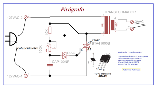
There is another approach that requires a bit more electronics knowledge:

This one doesn't supply a part number for the transformer, but it is essentially the same thing. The dimmer block is now broken out as a Triac controlled by a potentiometer. I looked for a 60Hz power transformer at Digikey, but did not find anything with the required current capability.
I was not aware of any of these simple schemes, so I just plowed ahead with my own concepts.
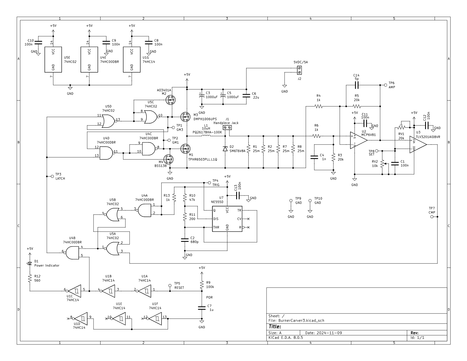
The 6V Burner Schematic (now obsolete):

When power is applied, the converter is held in reset by U1B for a few ms in order to let the power supply (6VDC/6A) stabilize. The NE555 generates a 200ns pulse approximately every 30us which sets the R-S latch and turns on the top PFET (M3). This causes the current to increase in the inductor, L1. This current develops a voltage across the 25mR parallel resistors, R1-2 and R7-8, which is then amplified 20x by U2. When the output voltage of U2 exceeds the set point voltage controlled by RV2 (and the user) then the comparator, U3, trips and causes the R-S latch to reset. The R-S latch is then reset, M1 is turned on, and the current in L1 decreases until the cycle repeats with another pulse from the NE555. I'm not planning to have any heatsinks. The power dissipation when applying 15A to the handpiece is less than 3W, which should be acceptable.
The gates U5C, U5D, U4C, U4D prevent shoot-through currents between M3 and M1. The huge 1000uF electrolytic capacitors have very low ESR (26mR) and are there to absorb the 15A peak currents to make it easier for the 5VDC power source to keep up.
I found a relatively cheap 5VDC/6A AC/DC adapter on Amazon for around $13. I modified it to produce 6VDC @ 6A. The handpiece could be had from Amazon for about $12-$18, or a bit less from AliExpress. I printed an enclosure using Thingiverse "Advanced Ultimate Box Maker" that is working nicely. I'll make the .stl files available.
When I added up the BOM for the custom electronics and enclosure the total outlay came to around $60, which is not bad when compared to the commercial offerings available.
A 12V Version:
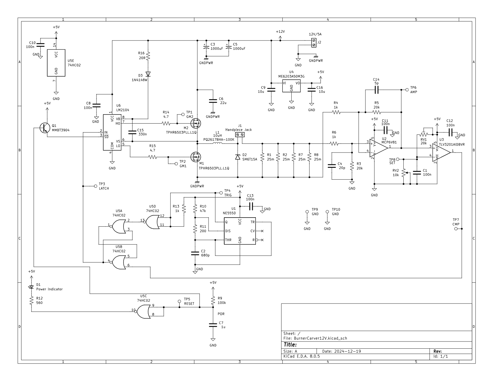
The burner was pushing the 5VDC adapter pretty hard -- more than 6A for a 20AWG tip. Also, the 5VDC/6A adapter is not very common, but there are lots of 12VDC/5A adapters available at reasonable prices (~$10). So I redesigned the burner to accommodate 12V and here's the result:

In order to drive the gates of the FETs at 12V I'm using a LM2104 gate driver IC ($0.42/each in a SOIC8 package). The LM2104 has a boosted top gate drive for an NFET, so now there are two identical 0.6mR NFETs. The gate driver takes care of all of the shoot-through and level shifting, but needs a minimum of 8V and maxes out at 18V, which is perfect for this design. It also has a shutdown input to prevent switching, which saves a bit of circuitry. Use of the gate driver eliminates two logic ICs. But the analog and remaining logic require a LDO regulator for their power. A 3-terminal LDO is used for the 5V rail -- either an MCP1799 or ME6203. Both LDOs will handle up to 40V input and consume uA of current. Other than those changes the rest of the circuit is identical.
Simulation predicts a reasonably good efficiency -- around 87% with 15A through the burner tip. The downside is that the converter will skip quite a few cycles at currents below 1A. Hopefully, that won't create an audible issue, but there isn't much use for currents that don't heat the tip to a usable temperature.
With 60W to play with I increased the output current specification to 20A.
Project Status
[2024-12-12] The second pass PCB prototypes appear to work well. All is well that ends.
[2024-12-17] 12V version PCBs are ordered and awaiting fab. I ordered the LM2104, and a few more TPHR6503 NETs, from Digikey.
[2025-02-06] 12V version works as expected. I don't think any changes are warranted (except maybe reducint max current from 20A to 15A.
 Bud Bennett