 janusprotocol
I designed the first iteration of this board knowing that I've probably got a lot of things wrong in the design, so I included a few features to help me diagnose what's going on. Unfortunately I got many of those circuits wrong too, womp womp. However, I was able to get the board working both to receive and transmit.
First, the issues:
1) I found that powering the SA868S-V module with 5 V was problematic, leading to the module being locked into transmit unless 5 V was delivered to the PTT pin, and even when PTT was grounded (which should enable transmission) not even a carrier wave was being detected. When I swapped the module to 3.3 V all these issues went away. To make this permanent, I cut the 5 V pin off the board and soldered a botch wire from the 3.3 V pin (which wasn't connected to anything on the board) to the vacant 5 V pin hole.
2) Microphones need electricity to work (derp) and the microphone circuit concept I had in my head was simply incorrect. When designing this board, however, I connected a pin to the microphone in trace via a 0 ohm resistor, which when soldered would act to connect a FZ pin directly to the MIC for transmission of stored audio or digital signals. Another 0 ohm resistor was already in place connecting the microphone in from the TRRS jack to the module, so that was replaced with a 10 uF ceramic 0603 size capacitor, while the previously mentioned 0 ohm resistor was replaced by a 10 kiloohm resistor. Finally, I soldered a botch wire from the 3.3 V pin to the mic pin that sits on the other side of the new 10 K resistor.
3) I didn't know that the TX line in a UART serial connection is held high; this meant that my Tx/Rx LEDs were kinda useless, so I removed those components. Also, the inverter I designed to convert the 1 > Rx, 0 > Tx to an LED that's on when PTT is enabled was a total wash, so it got removed too. I decided that the redesign will use a small NOT gate IC to drive the PTT indicator LED.
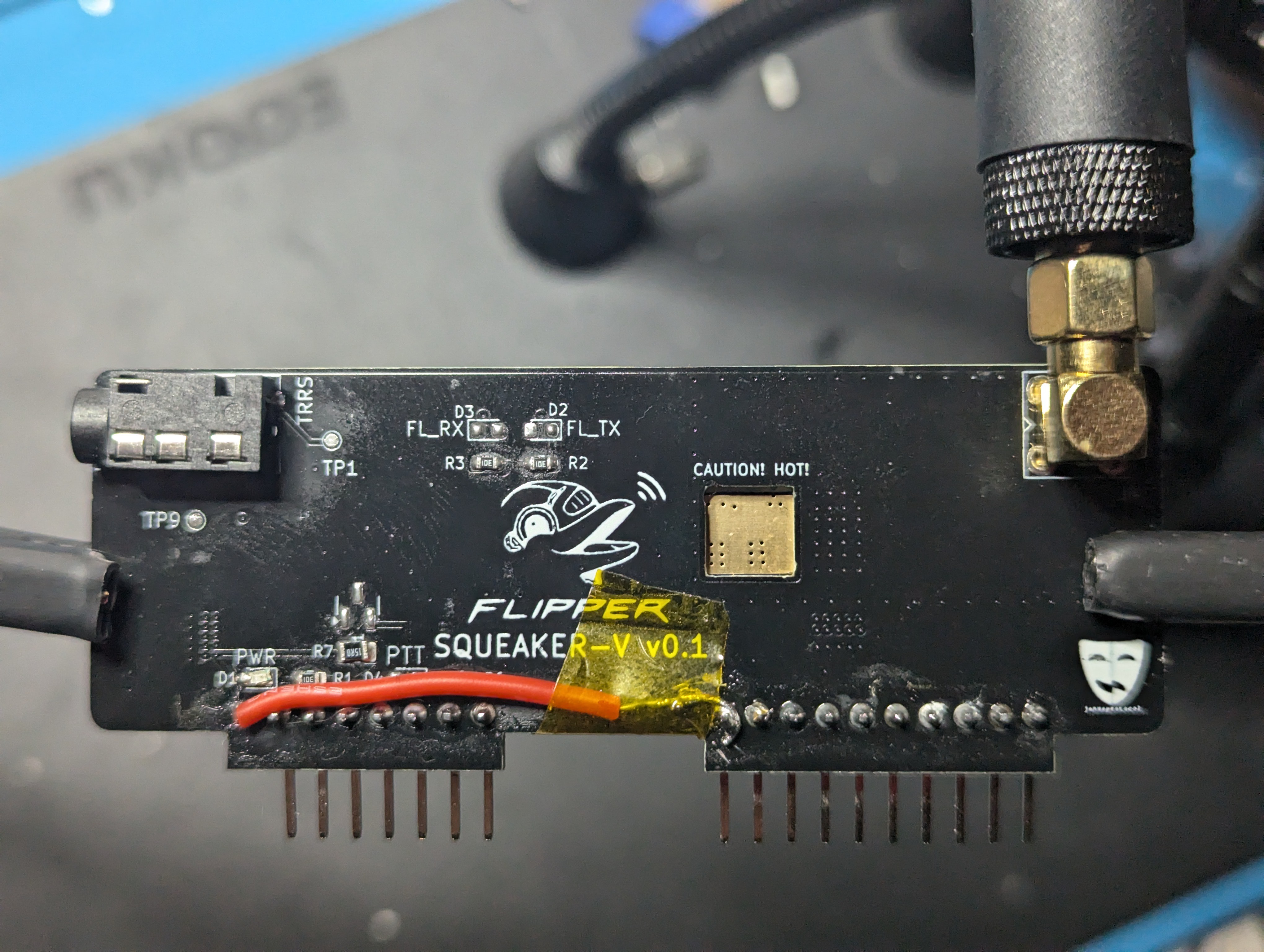

(These pictures make this board look way filthier than it actually is, no idea why)
With these solutions in place, I was able to successfully transmit! I redesigned the board to incorporate these changes, and will be ordering it sometime in the near future. Now that I have a working prototype board, however, I'm going to focus on writing the application for the FZ to drive the board and issue commands to the MCU in the SA868 module. That'll take a while because, as I mentioned previously, I don't speak C++ so I'm learning that while I write the app.
Discussions
Become a Hackaday.io Member
Create an account to leave a comment. Already have an account? Log In.