 Stephen Holdaway
Rev 2 boards arrived yesterday. This was my first order from JLCPCB, and the PCBs seem to be decent quality. Shipping time to New Zealand was excellent at just 3 days! I've previously used SeeedStudio, but their shipping charge was extortionate at $60 USD for this order, so I figured I'd try JLC.


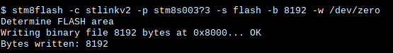
Working in the smallest blocks possible, I first attached the STM8S chip and a few capacitors to verify the micro could be programmed on the board. Immediately had to troubleshoot a short across VCC and GND which turned out to be a dead 0602 capacitor - I'd apparently overheated it with hot air. Switched to using the soldering iron, replaced the capacitor, and the programmer could write to the chip fine:
It's nice that the STM8 chips don't require any external components to test. Their reset circuitry is internal, and aside from a couple of capacitors there's nothing you can really miss that will prevent it from working.

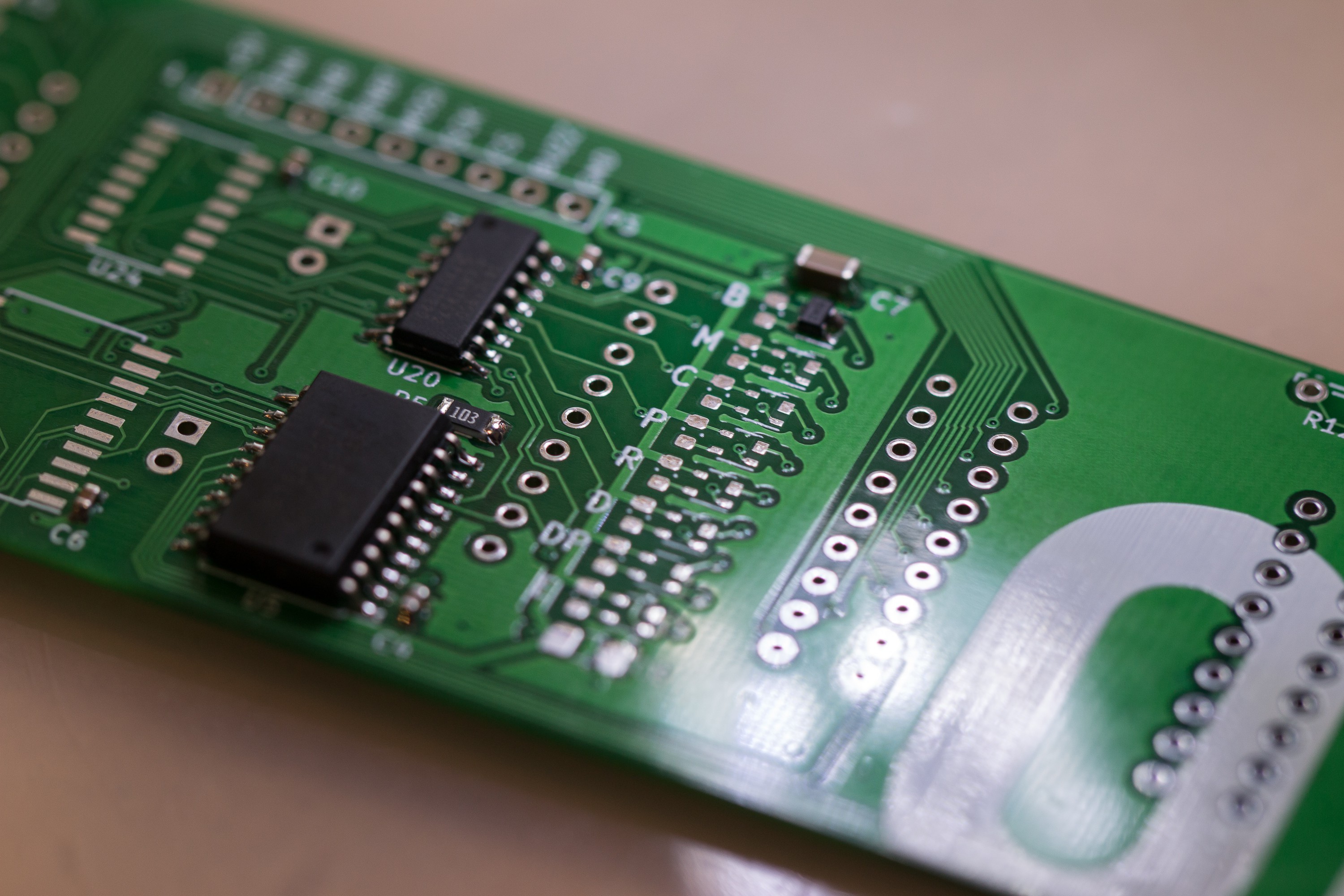
Next I added the minimum components needed to control a single segment: one each type of shift register, a bunch of passives and one of the LED driver chips.
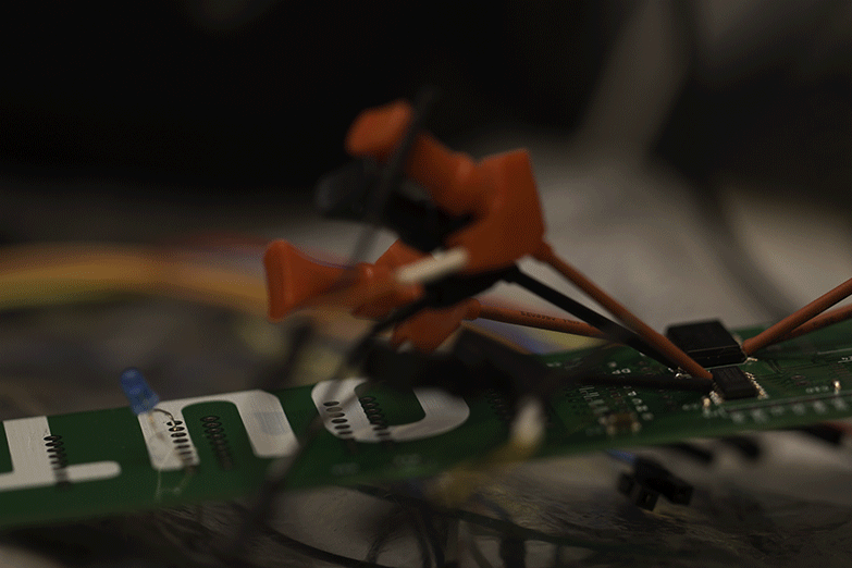
I hadn't pre-written any code for this driver, but after about an hour with the help of a logic analyser to help me spot stupid late night mistakes, I had control of a single segment on 8 digits:

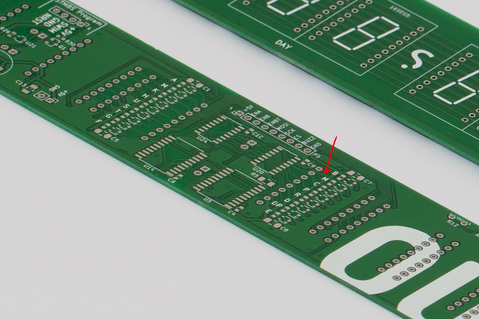
It's certainly nice to know that nothing fundamental is messed up, though I did spot a silkscreen error I missed: One of the segment names by one of the LED drivers is "M" instead of "N".
Taking a lesson from rev 1, I won't be soldering any of the 16 segment displays until I've verified the board is completely working. De-soldering a dozen 16 segment displays was a particularly unpleasant experience and it's not a process I want to repeat again.
Next step is to add the remaining segment drivers and confirm that's working, then add the remaining components outside of the main driver: AM, PM and time-separator drivers, the buzzer and pin headers.
Discussions
Become a Hackaday.io Member
Create an account to leave a comment. Already have an account? Log In.