 Stephen Holdaway
After a few more evenings with this project, it's technically working, but the display isn't as bright as I'd like.
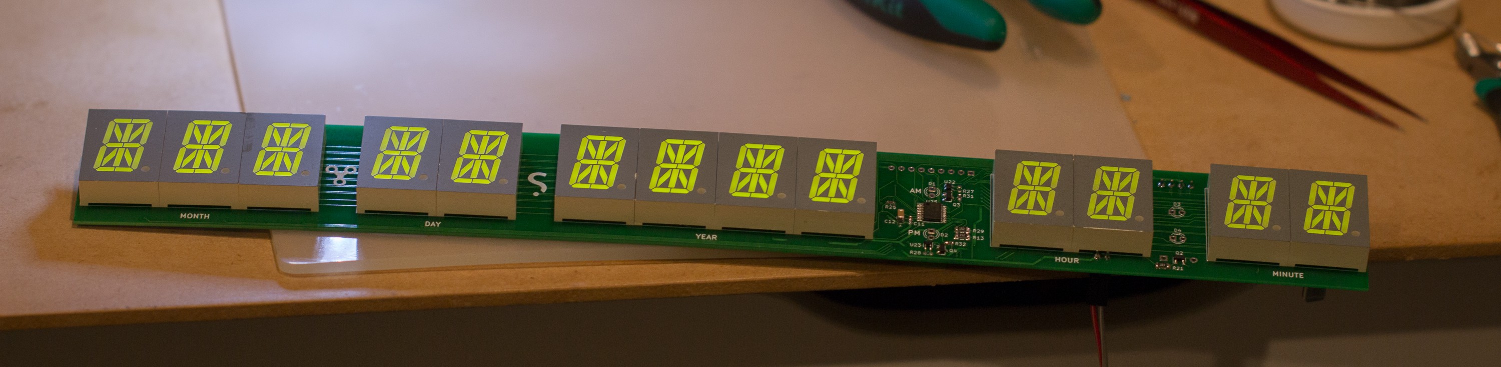
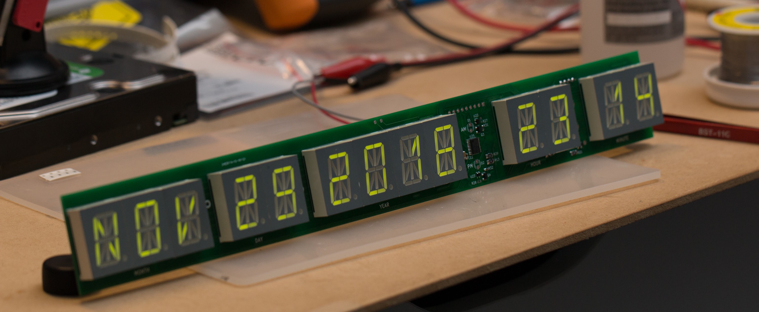
Here's a quick update in photos:
Making it brighter
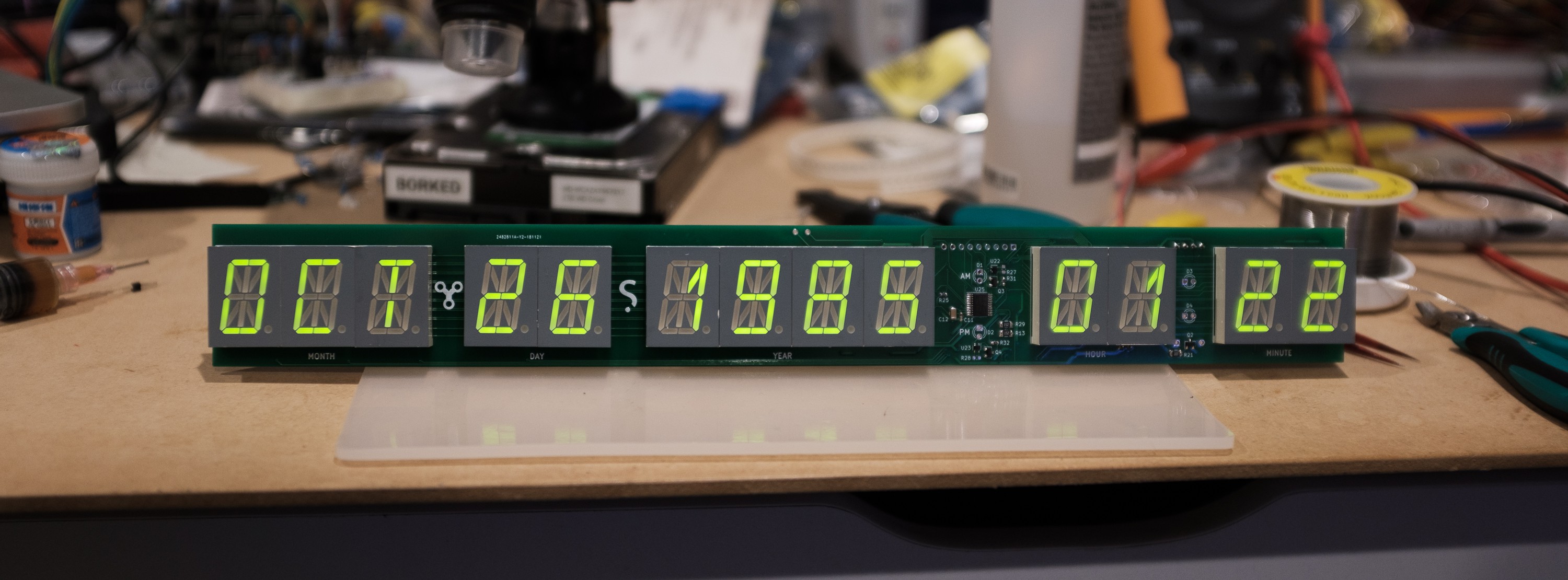
The display looks pretty bright in the above photos, but that's mostly from dim ambient light combined and the camera's ISO ramped up to compensate. Under daylight indoors, it looks more like this which isn't ideal:
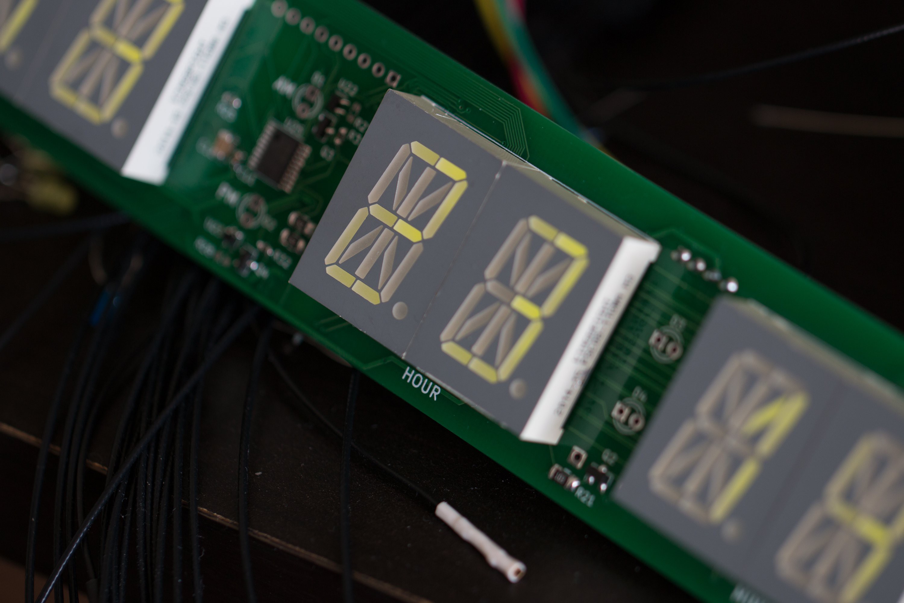
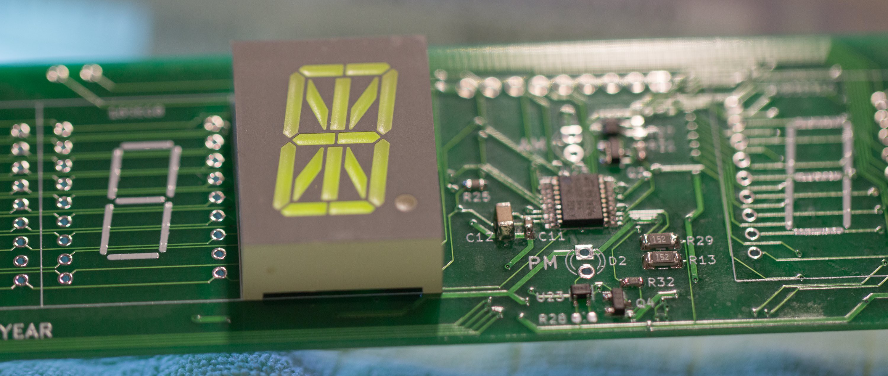
The digits are lit one at a time with all of their configured segments, making the duty cycle around 1/13. The display is a good brightness when driving 4-6 digits only, and the segments are plenty bright when not multiplexed, so the dimness is definitely multiplexing related.
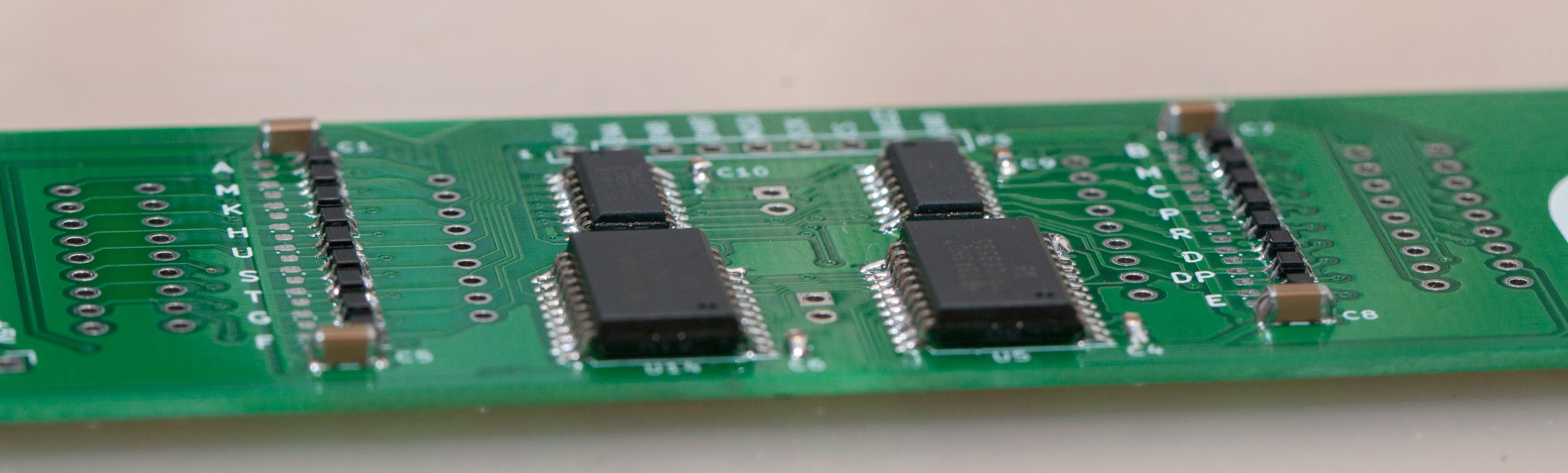
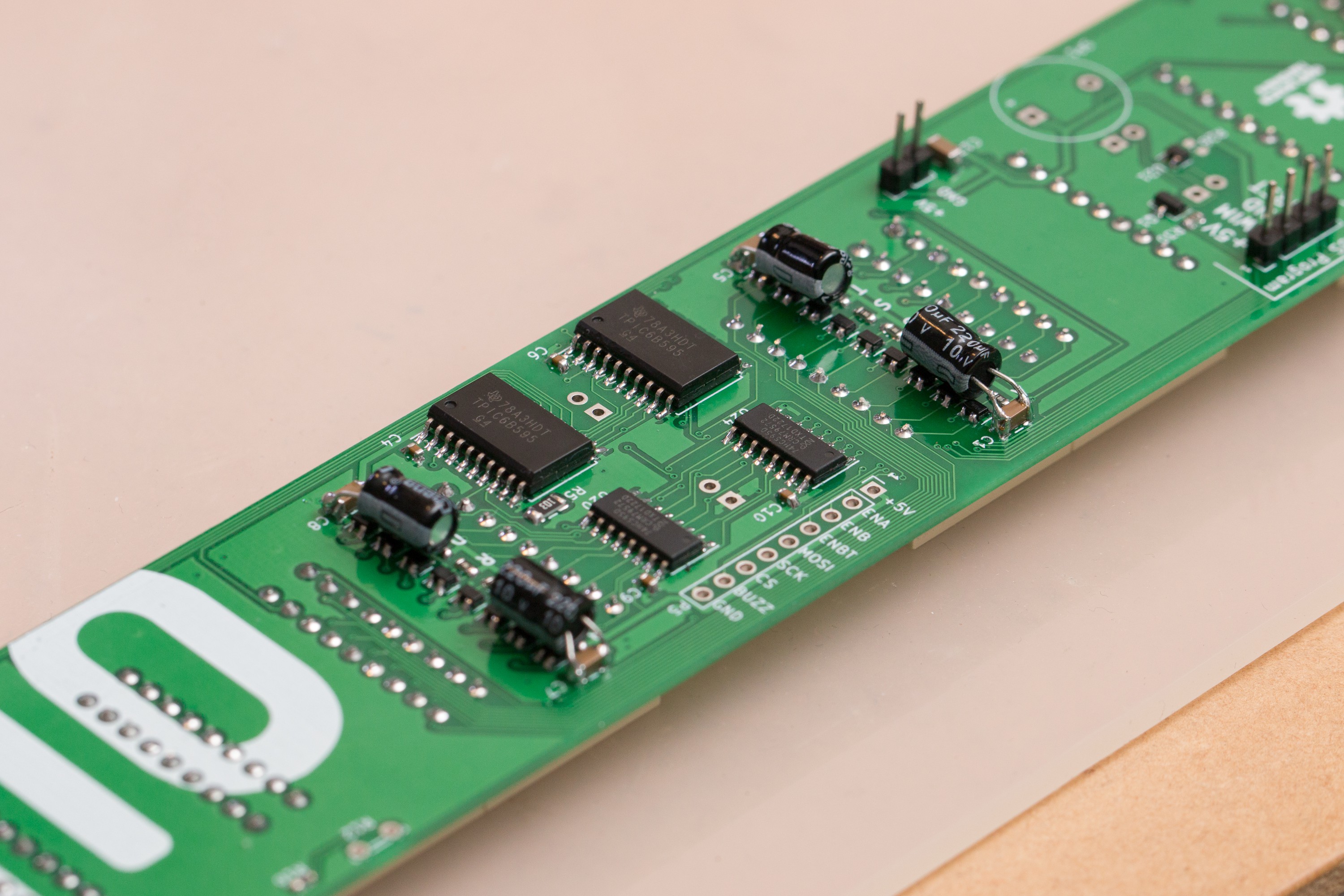
The optional external resistor on each LED driver IC allows configuration of up to 60mA driving current, instead of the default 20mA. Chucking in some low value resistors to get the LED drivers to 60mA did help a little, though the segments are unevenly lit now as I only had "10%" tolerance resistors lying around:
With this higher current demand, I also had to chuck on a bunch of extra capacitors:
I'll keep working away at this as I'd really like the display to be brightly visible indoors during the day (not in direct sunlight, just bright ambient light).
Increasing the voltage supplied to the LED drivers would work very well to solve this, but this doesn't seem feasible due how I'm controlling the LED drivers; since the 5V is supplied for the "segment off "state rather than the pin going high-Z, the LED driver would turn on in the off state (current can sink from the >5V supply into the 5V being supplied). I tested this on the bench with a loose driver IC, and it turns on even with +Vs at 6V and GND at 5V.
If I can't find another solution, I may be tempted to hack the two spare TPIC power shift registers I have into the place of the 74HC595D's so this higher drive voltage for the LEDs would work...bit of a last resort bodge to do that though.
Discussions
Become a Hackaday.io Member
Create an account to leave a comment. Already have an account? Log In.