 Stephen Holdaway
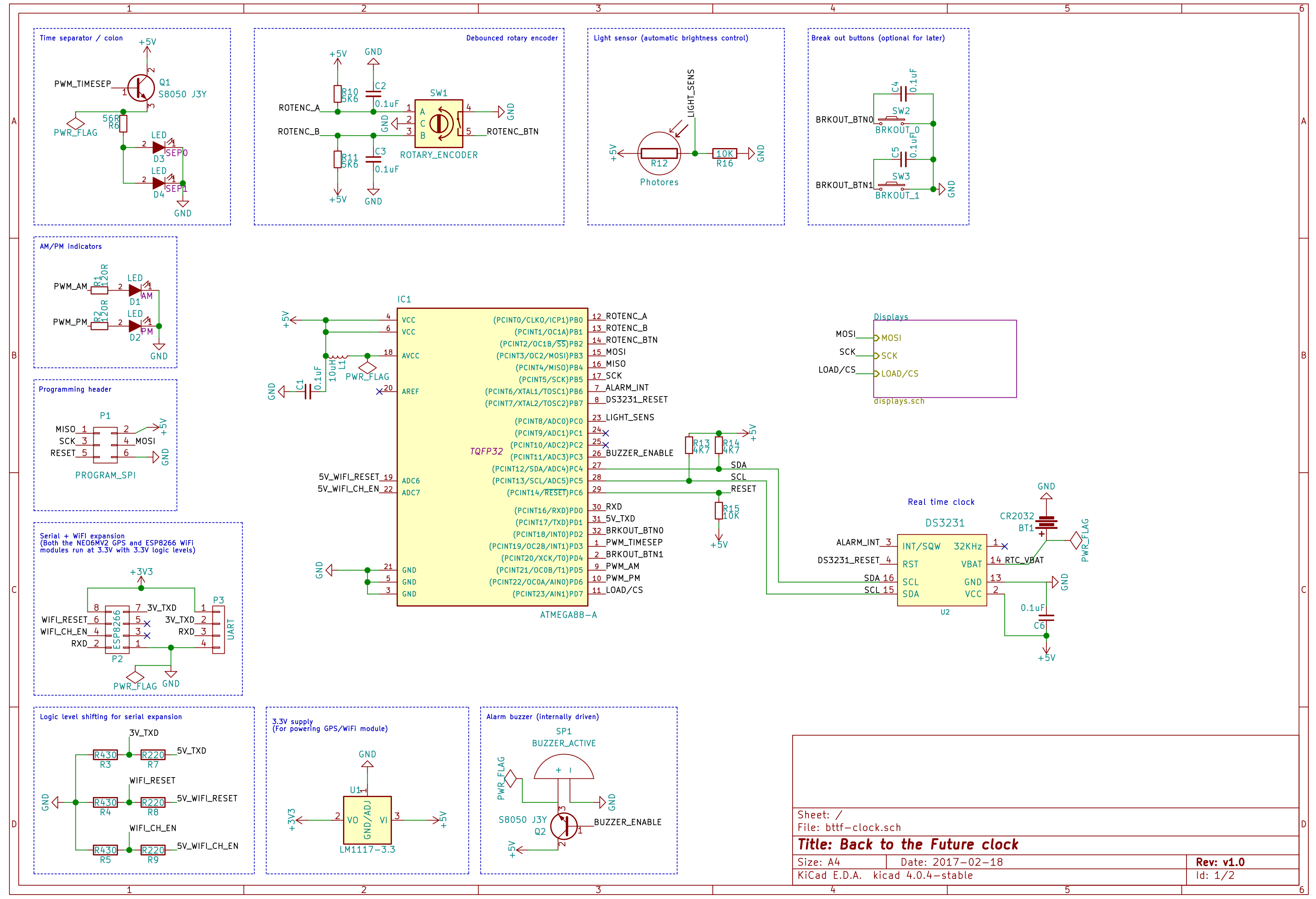
Schematics with KiCad! Previously I've used Eagle, but as this was originally going to be a single 300mm x 40mm board, Eagle wasn't going to work with its restrictive board size limits. I'm currently deciding whether to have a few smaller boards or one large one. Smaller boards are easier to mask and etch by hand, and errors are less costly, so if I can route these display boards single sided I'll just etch them myself.
The plan for multiple display boards is this, where the IC icons represent which boards hold which driver chips:
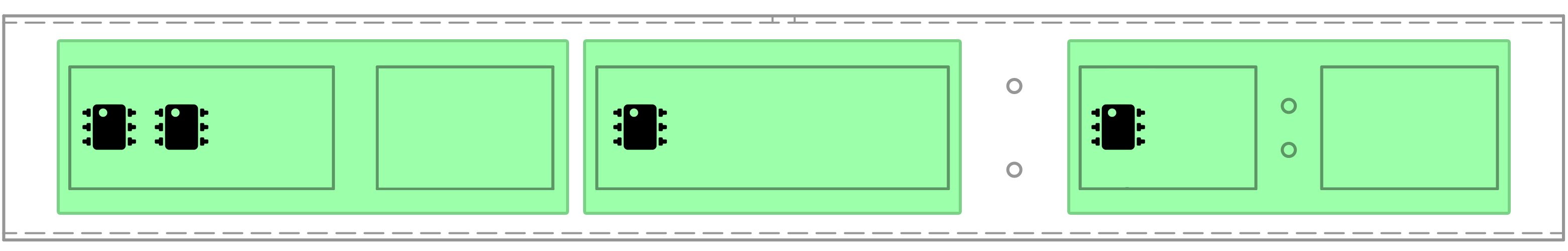
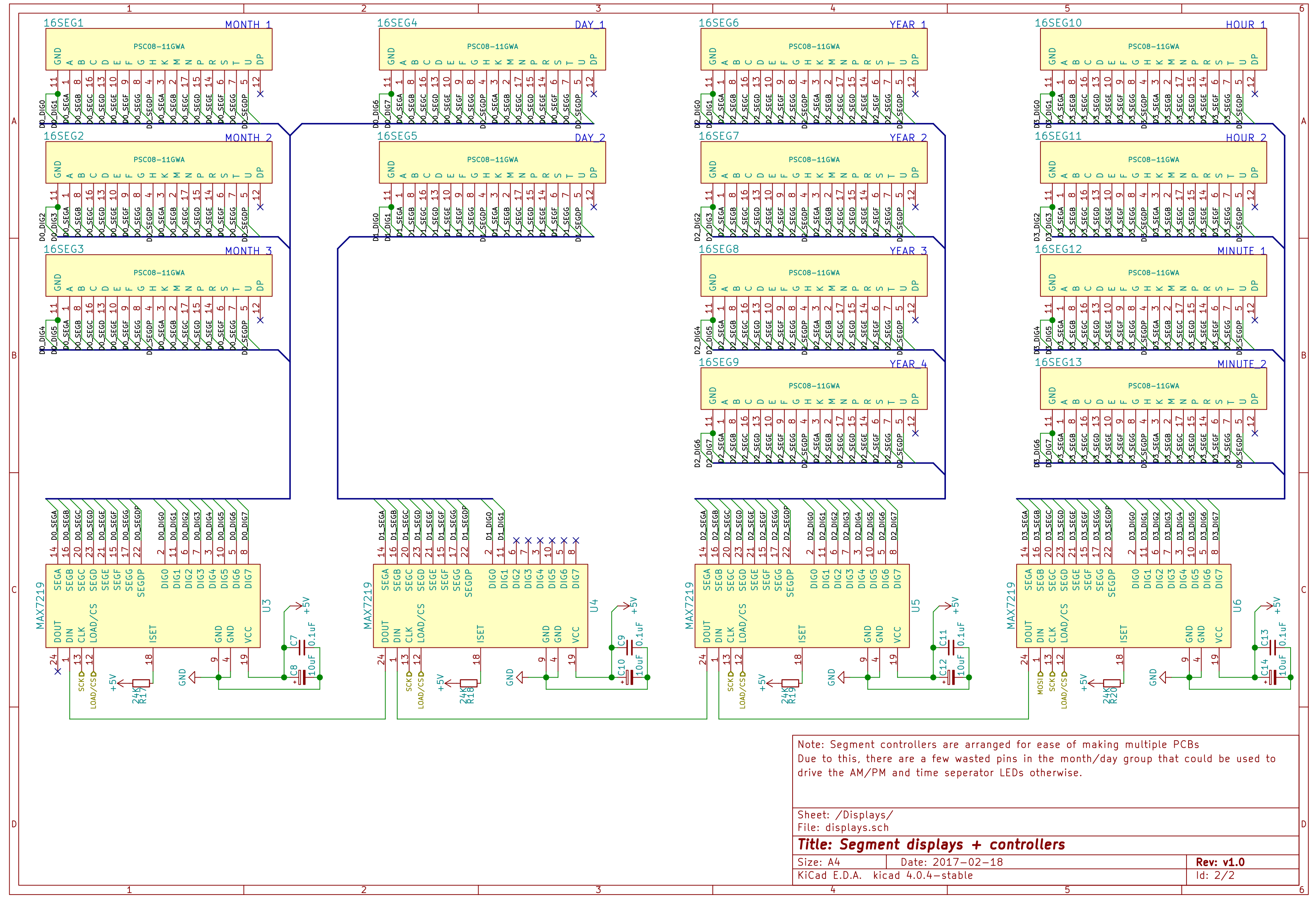
By having driver chips only connected to segments on their own PCB, there's just five connections to make between each board (VCC, GND, DIN/DOUT, CLK, LOAD). The schematic is wired assuming this layout.
Design notes so far:
- This has to run at 5V as the MAX7219 chips don't support a lower voltage
- I'm using the internal 8MHz oscillator in the Atmel ATMEGA88 rather than an external one
- At one point the AM/PM and time separator LEDs were connected to spare outputs on last MAX7219. Since the multiple boards plan moves the spare outputs to the left side the enclosure however, I've opted to use three PWM outputs from the MCU rather than running wires the length of the enclosure.
Discussions
Become a Hackaday.io Member
Create an account to leave a comment. Already have an account? Log In.