 agp.cooper
Basic Components of a PLL
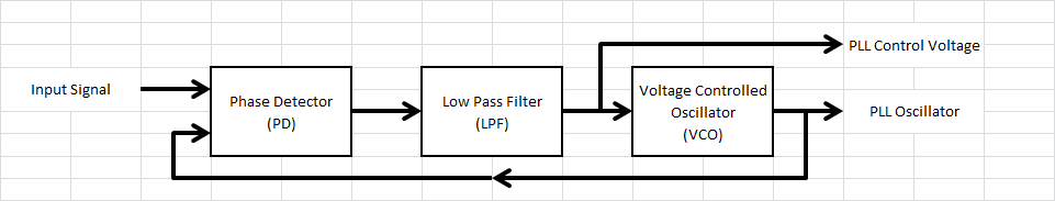
The basic components of a PLL are:
- Phase Detector
- Low Pass Filter
- Voltage Controlled Oscillator
Optionally:
- Divide by N Counter
- Output Low Pass Filter
Here is my basic PLL diagram:
The Phase Detector
There are a number of different types of phase detectors (PD). The most common are:
- XOR
- Edge detector
- Multiplier
I am only looking at the XOR (exclusive OR) detector here. If you are not aware, the XOR is a logic gate (i.e. 7486):
 This can be modelled as:
if (A==B) {
  PD=0;
} else {
  PD=1;
}
Or more compactly as:
PD=(A==B)?0:1;A PLL needs some DC loop gain (usually refer to as Kpd*Kvco). For this PLL all the loop gain (PK) is provided by the PD (phase detector). The main reason id that an integer maths digital low pass works best with higher values (i.e 0 and 1 will not cut it).
So here is the final PD:
PD=(A==B)?0:PK;The Low Pass Filter
Here is a simple RC low pass (LP) filter:
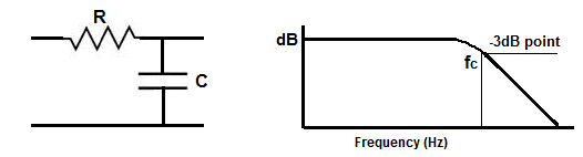 (source: www.learningaboutelectronics.com/images/Low-pass-filter-diagram.png)
A simple RC low pass has a corner frequency (Fc) of:
- Fc = 1/(2*Pi*R*C)
This can modelled as:
- LP = a*LP+(1-a)*PD
(You may recognise this as the exponential smoothing equation)
Where:
- a = Exp(-2*Pi*Fc/Fs)
Where Fs is the sample frequency (Fs).
This can be reworked as:
LP=LP+A*(PD-LP)/DWhere a = A/D, where A is an integer and D is a power of 2 (i.e. 2, 4, 8, ...).
The reason for D being a power of 2 is that division is expensive for the Arduino and arithmetic shift right (>>) is not.
Although the RC LP filter works the voltage response and can oscillate and a "Lead-Lag" filter is usually preferred as it has a faster response with less overshoot:
(source: mysite.du.edu/~etuttle/electron/circ116.gif)
I have yet to "digitised" the Lead-Lag loop filter (TBC ...).
The Digital Oscillators
The generation of a both the test signal (SX) and the PLL oscillator (PX) are based on the Direct Digital Synthesis (DDS) . I will uses a 16 bit phase accumulator both the signal and PLL accumulators (SA and PA). The tuning words (SM ans PM) are:
- SM = SF*2^16/Fs, where SF is the signal frequency
- PM = PL*2^16/Fs, where PL is the low PLL oscillator frequency
The DDS's are:
- SA=SA+SM
- PA=PA+PM
Note: that overflow does nor cause and error.
And to get the binary output frequency:
- SX=SA<<15;
- PX=PA<<15;
To increase the PLL oscillator frequency we add the LP output to the phase accumulator:
- PA=PA+PM+LP
So what have we done? The PLL VCO low frequency is set by PM and the high frequency by is set by PM+LP, as the LP values range from 0 to PK.
The maximum PLL VCO frequency (PH) is then:
- PH=PL+PK*FS/2^16
So magic, we can estimate PK from the difference between the required VCO high and low frequencies.
The two equations above code as:
SA=SA+SM;
PA=PA+PM+LP;
Here is the code written in Excel VBA:
Option Explicit
Sub PPL()
Application.ScreenUpdating = False
Application.Calculation = xlCalculationManual
Application.EnableEvents = False
Dim Pi As Double
Pi = 4 * Atn(1)

Dim FS As Long   ' Sample Frequency
Dim SX As Long   ' Sample Input
Dim SF As Long   ' Sample Frequency Frequency
Dim SA As Long   ' Sample Frequency Phase Accumulator
Dim SM As Long   ' Sample Frequency Phase Increment
Dim PX As Long   ' PLL Frequency
Dim PL As Long   ' PLL Low Frequency
Dim PM As Long   ' PLL Phase Increment
Dim PA As Long   ' PLL Phase Accumulator
Dim PD As Long   ' PLL Phase Detector
Dim PK As Long   ' PLL Phase Detector Gain
Dim LP As Long   ' Low Pass Filter
Dim LPF As Long  ' Low Pass Filter Corner Frequency
Dim LP2 As Long  ' Output Low Pass Filter
Dim A As Long    ' Low Pass Filter Constant
Dim D As Long    ' Low Pass Filter Divisor
Dim Time As Long ' Time Step

FS = 12000
SF = 1070
SM = SF * 65536 \ FS
SA = 0
SX = 0

PL = 800
PM = PL * 65536 \ FS
PA = 0
PX = 0
PK = 5000
PD = 0
LP = 0

PK = Int(ActiveSheet.Cells(1, 10).Value + 0.5)
LPF = Int(ActiveSheet.Cells(2, 10).Value + 0.5)
D = 128
A = Int(D * Exp(-2 * Pi * LPF / FS) + 0.5)

ActiveSheet.Cells(1, 1).Value = "Time"
ActiveSheet.Cells(1, 2).Value = "FX"
ActiveSheet.Cells(1, 3).Value = "SX"
ActiveSheet.Cells(1, 4).Value = "PX"
ActiveSheet.Cells(1, 5).Value = "PD"
ActiveSheet.Cells(1, 6).Value = "LP"
ActiveSheet.Cells(1, 7).Value = "LP2"
For Time = 0 To 240

  ' Sample Frequency (300 baud binary pattern)
  If (Time Mod 80 = 0) Then
    SF = 1070
    SM = SF * 65536 \ FS
  End If
  If (Time Mod 80 = 40) Then
    SF = 1270
    SM = SF * 65536 \ FS
  End If

  SA = SA + SM
  If (SA >= 65536) Then SA = SA - 65536
  SX = SA \ 32768

  ' PLL FREQUENCY
  PA = PA + PM + LP
  If (PA >= 65536) Then PA = PA - 65536
  PX = PA \ 32768

  ' XOR PD
  If (SX = PX) Then
    PD = 0
  Else
    PD = PK
  End If

  ' PLL LPF (Fc = 100 Hz)
  LP = PD + A * (LP - PD) \ D

  ' Output FIlter
  LP2 = LP + A * (LP2 - LP) \ D

  ' Plot results
  ActiveSheet.Cells(Time + 2, 1).Value = Time
  ActiveSheet.Cells(Time + 2, 2).Value = SF
  ActiveSheet.Cells(Time + 2, 3).Value = SX
  ActiveSheet.Cells(Time + 2, 4).Value = PX
  ActiveSheet.Cells(Time + 2, 5).Value = PD \ PK
  ActiveSheet.Cells(Time + 2, 6).Value = LP
  ActiveSheet.Cells(Time + 2, 7).Value = LP2
Next Time

Application.ScreenUpdating = True
Application.Calculation = xlCalculationAutomatic
Application.EnableEvents = True
End Sub
Here is a plot with PK=5000:
I have to say it does a pretty good job decoding the a FSK signal. A Lead-Lag filter should fix the initial over-shoot and speed up the response.
The mid point for the output signal (LP2) should be:
- LP = (1170-800)*65536/1200
- = 2021
Which matches the plot.
AlanX
Discussions
Become a Hackaday.io Member
Create an account to leave a comment. Already have an account? Log In.