 agp.cooper
Optimisation
I have been considering what to do next with the software PLL. Do I go the simple low pass filter and move on or spend more time optimising. It is a question of time versus likely outcomes. I have a good result, is it worth trying to make it better?
The second problem is how to optimise this problem? I can see two approaches:
- More theoretical research - Someone else may have already solved this problem.
- Use numerical methods to search the parameter space (maybe I will get lucky).
But first what is the problem I am trying to solve?
Here is a very good result from the Bell103A2 modem project:

What are the key attributes:
- a sine wave response with a period of 150 Hz
- centred around known mid point (zero in this case)
- the sine wave peaking at the end of the bit width pulse
- a smoothed square wave for longer pulse widths
- both the sine wave and smoothed square wave peaking at the maximum value
- the absence of noise at the peak values particularly for the smoothed square waves.
Here is a less than ideal response:

Back to phase locked loops
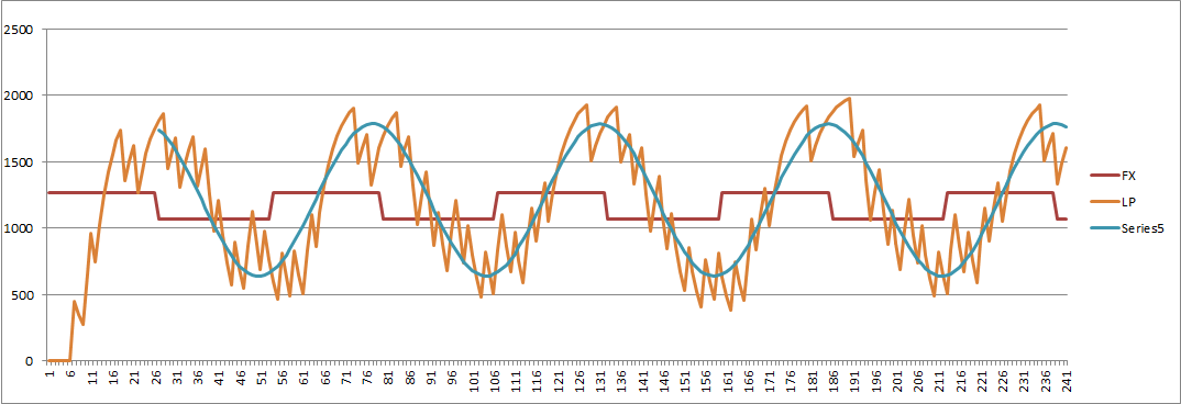
Here is my current low pass PLL response showing the data input (square wave), the LP output and a fitted sine wave:
So why is this important? Here is version that looked good in the beginning only to blow up latter:
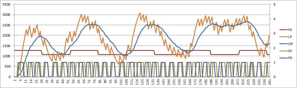 What when wrong?
Searching Parameter Space
What controls the output of the PLL? Yes I know about Q (transit overshoot) and natural frequency but the above image shows a stable PLL becoming unstable. To fix the above I increased the lower bound frequency to reduce the work for the PLL to get into lock.
What parameters can I play with?
- sample rate
- low frequency
- low pass filter frequency
Sample Rate
I am obviously very reluctant to change (increase) the sample rate. But here is the impact (SR = 8065):
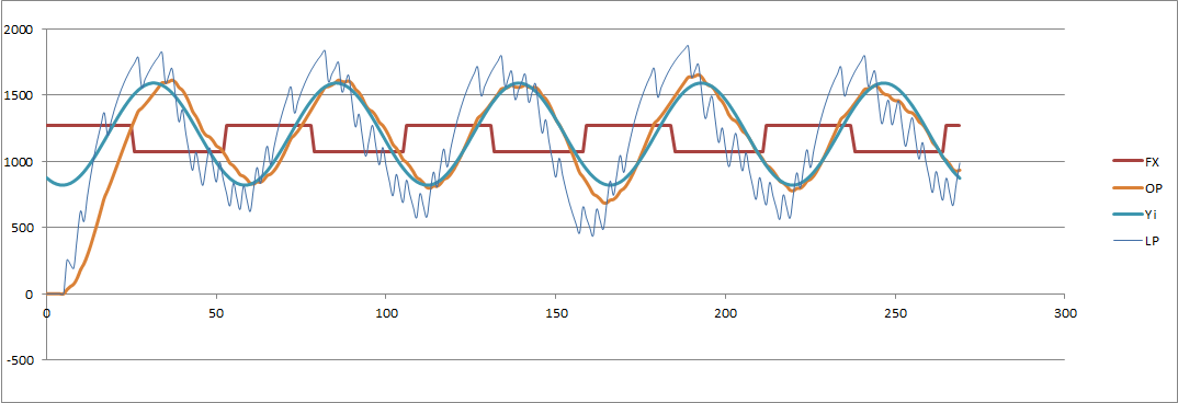
And (SR = 16667 Hz):
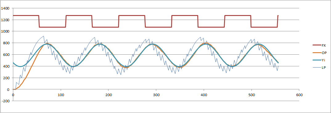
Note: the fitted sine wave (to the output) uses the last four cycles.
DDS Low Frequency
I already know this works but I don't know if the system is stable?
Low Pass Filter
Again, yes but the theory does not translate very well with a low sample rate.
What to do?
I am thinking that I could get really bogged down here. I have coded a steepest descent optimiser (but not run it ) but based on the rules of thumb that I already know I suspect I will not find anything new. The problem has multiple local optima (due to the discrete nature of a software PLL), so problem will not solve easily or reliable. I think I should move on!
Fitting a Sine Wave to the Data
I am familiar with multi-variate analysis so linearising and solving the equations is not too hard. The form of the equation I am trying to solve is:
- Y = A + B * Sin(2 * Pi * F * t + P)
where:
- B is the amplitude (to solve)
- F is the frequency (known, that is 150 Hz)
- P is the phase (to solve)
- A is the offset (known but will solve anyway)
Separate the Frequency and Phase using:
- A + B * Sin(2 * Pi * F * t + P)
- A + B * Cos(P) * Sin(2 * Pi * F * t) + B * Sin(P) * Cos(2 * Pi * F * t)
Therefore (after relabelling the constants):
- Y = A0 + A1 * Sin(2 * Pi * F * t ) + A2 * Sin(2 * Pi * F * t )
The error squared function is:
- E2 = (Y - (A0 + A1 * Sin(2 * Pi * F * t ) + A2 * Sin(2 * Pi * F * t ) ))^2
Solving the multi-variate problem:
- Sum(Y) = A0 * (N + Sum(Cos(2 * Pi * F * t)) + Sum(Cos(2 * Pi * F * t)))
- Sum(Y * Cos(2 * Pi * F * t)) = A1 * (Sum(Cos(2 * Pi * F * t)) + Sum(Cos(2 * Pi * F * t) * Cos(2 * Pi * F * t)) + Sum(Cos(2 * Pi * F * t) * Sin(2 * Pi * F * t)))
- Sum(Y * Sin(2 * Pi * F * t)) = A2 * (Sum(Sin(2 * Pi * F * t)) + Sum(Cos(2 * Pi * F * t) * Sin(2 * Pi * F * t)) + Sum(Sin(2 * Pi * F * t) * Sin(2 * Pi * F * t)))
Where N is the number of samples.
Fortunately the above simplifies if the range of "t" is a multiple of 2 * Pi, to:
- Sum(Y) = A0 * N
- Sum(Y * Cos(2 * Pi * F * t)) = A1 / 2 / N
- Sum(Y * Sin(2 * Pi * F * t)) = A2 / 2 / N
Therefore:
- A0 = Sum(Y) / N
- A1 = 2 * Sum(Y * Cos(2 * Pi * F * t)) / N
- A2 = 2 * Sum(Y * Sin(2 * Pi * F * t)) / N
Here it is in VBA code:
A0 = 0
A1 = 0
A2 = 0
For Time = Int(SR / 150 + 0.5) To Int(5 * SR / 150 + 0.5)
  A0 = A0 + Test(Time)
  A1 = A1 + Test(Time) * Cos(2 * Pi * Time * 150 / SR)
  A2 = A2 + Test(Time) * Sin(2 * Pi * Time * 150 / SR)
Next Time

A0 = A0 / Int(4 * SR / 150 + 0.5)
A1 = 2 * A1 / Int(4 * SR / 150 + 0.5)
A2 = 2 * A2 / Int(4 * SR / 150 + 0.5)
E2 = 0
For Time = 0 To Int(5 * SR / 150 + 0.5)
  ActiveSheet.Cells(Time + 3, 8).Value = Space - 20
  ActiveSheet.Cells(Time + 3, 9).Value = A0 + A1 * Cos(2 * Pi * Time * 150 / SR) + A2 * Sin(2 * Pi * Time * 150 / SR)
  If (Time >= Int(SR / 150 + 0.5)) Then
    E2 = E2 + (Test(Time) - (A0 + A1 * Cos(2 * Pi * Time * 150 / SR) + A2 * Sin(2 * Pi * Time * 150 / SR))) ^ 2
  End If
Next Time
Back to the Modem Problem
Yes a PLL will work (quite well).
The other problem was removing jitter by extracting the clock. Well I have not really looked at that but I can now extract a fitted sine wave (with limitations) that could resolve much of the jitter. The error would be low on the transition and the fitted sine wave used to determine zero crossing. The computation effort though is not likely to work with the limited computational bandwidth of the Arduino CPU.
Regards AlanX
Discussions
Become a Hackaday.io Member
Create an account to leave a comment. Already have an account? Log In.