(project's sources and assets on GitHub: github.com/ncolomer/WaterTankMonitor)
Over the last months, I set out to turn an idea into a physical device: a water level monitor for my 5m³ water tank, connected via Zigbee and integrated with my Home Assistant.
This journey spanned PCB design, firmware development, 3D modeling, and assembly, all while navigating plenty of challenges and learning experiences.
In this write-up, I’ll walk you through the process, share the roadblocks I encountered, and detail how I overcame them, hoping it might serve as inspiration or guidance for other makers.
Initial Concept
The goal was to create a compact device that would regularly measure the water level in my 5m³ tank, display the fill percentage in my garage, and log data via Zigbee for smart home integration. Here were the main design constraints:
- PCB Design: The PCB needed to fit within a Legrand Mosaic obturateur, which meant using small components (e.g., SMT 0603, QFP) and compact connectors like JST XH.
- Reprogrammability: Given the anticipated need for multiple test iterations, I designed for quick and easy reprogramming by including both ICSP and FTDI ports on the board.
- Microcontroller Selection: I chose the ATmega328p for its compatibility with the Arduino framework, I2C, UART, Software Serial, ADC, and interrupts.
- Serial Protocols Only: I opted for UART communication, both for sensor and motherboard communication. This was to avoid analog coupling.
PCB Design
PCB design is both art and science, requiring meticulous attention to detail, datasheets, and wiring. It probably took me 3/4th of the time I allocated to the project. Here are the steps I went through.
You can find design and fabrication files here.
1. Concept draft
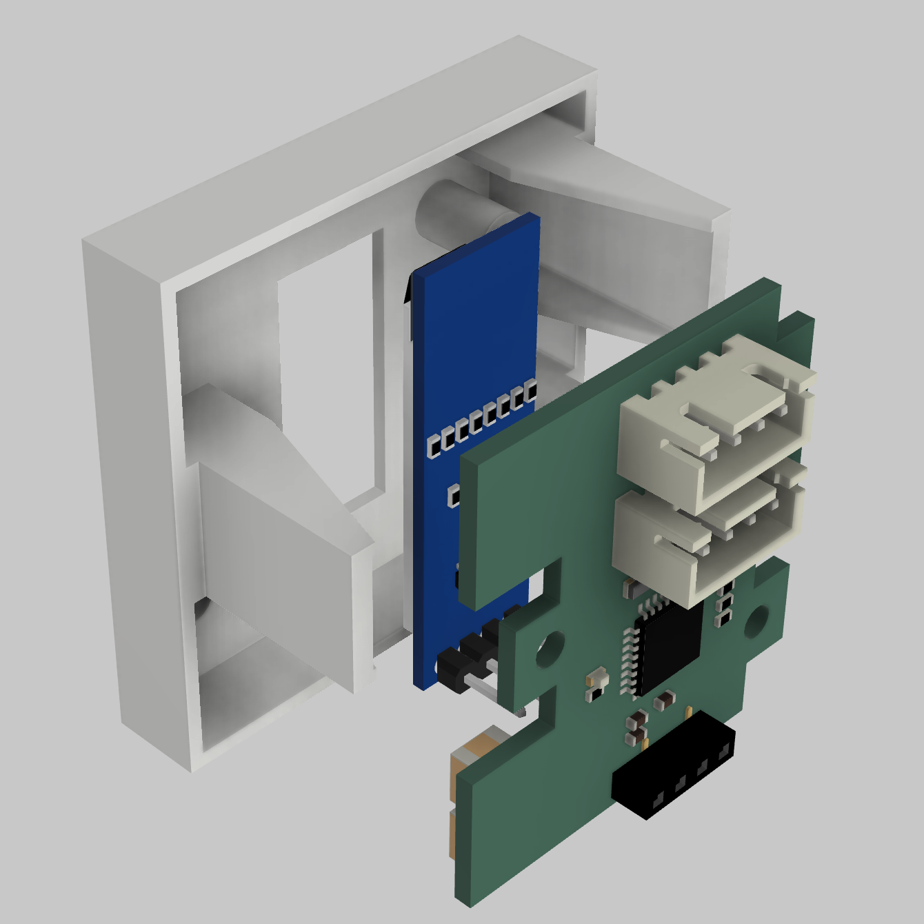
The very first step was to create a model of the Legrand Mosaic obturateur on Fusion 360. It allowed me to precisely measure some dimensions (like the PCB outilne or screw holes position) and get an overview of the final result.
Thanks to Kicad's 3D renderer, you can export your PCB as a STEP file. STEP is a commonly used file format containing three-dimensional model data. It can be imported into Fusion 360 and assembled with other parts.
2. Schematic Design
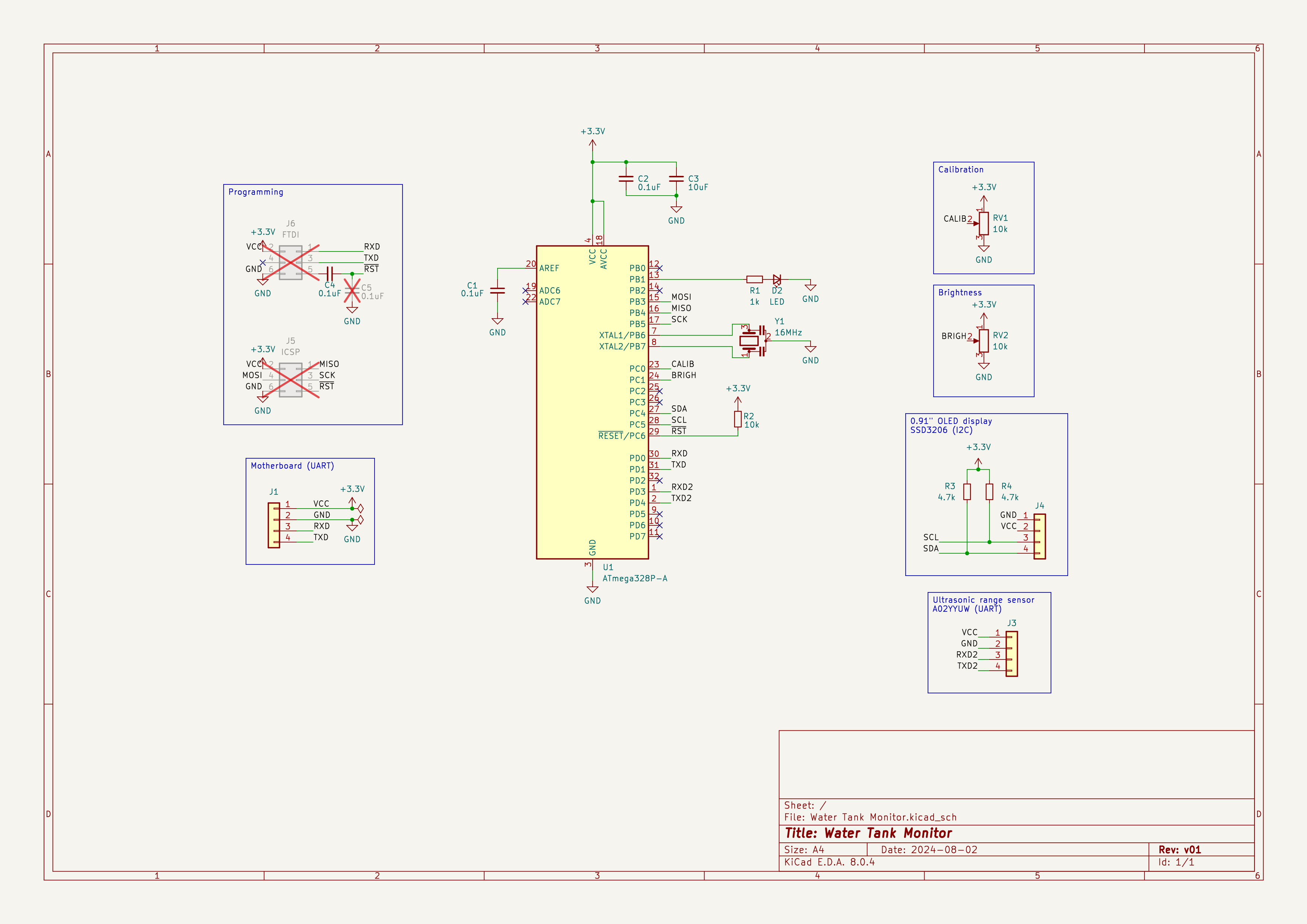
At its core, the device is an ATmega328p-based board with:
- A 0.91" OLED display using the I2C SSD1306 driver
- An A02YYUW ultrasonic range sensor (UART-compatible)
- Two manual calibration and display brightness potentiometers (though I replaced them later with a push-button)
- An onboard status LED
- UART connection to a PTVO-powered host
Open-source schematics like Arduino Nano and Moteino in addition to parts' datasheet helped me making most design decisions.
3. PCB Layout
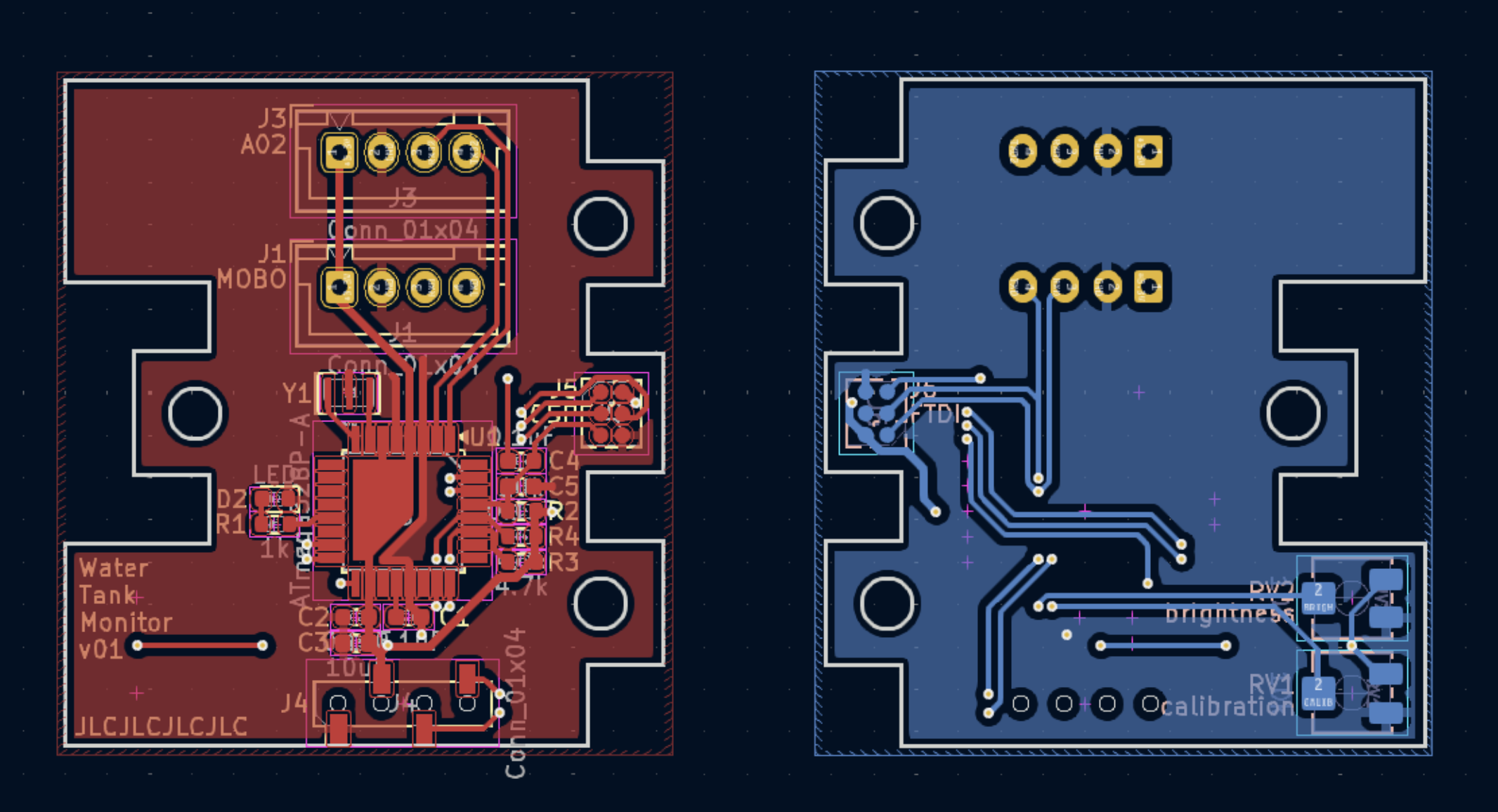
PCB layout was the most challenging phase of the project. It involves optimizing component placement, labeling traces, and factoring in both functional and physical constraints.
For programming, I placed two (ICSP and FTDI) 2x3 array of 1.27mm pitch SMD pads to be used with this pogo pin clamp I found on AliExpress.
Posting the board design on r/PrintedCircuitBoard yielded great tips, like minimizing trace length, avoiding isolated ground pours, simplifying power rails, and distinguishing power and signal tracks thickness.
4. PCB Fabrication & Assembly
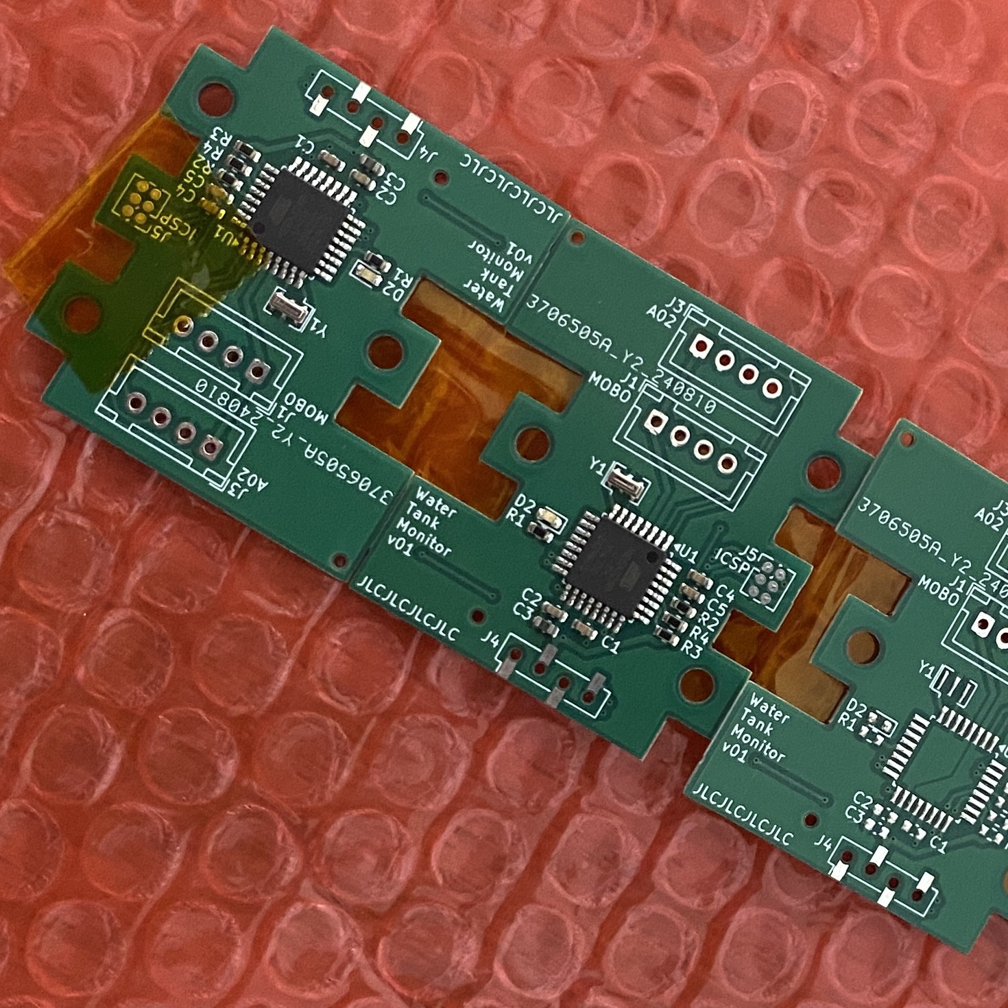
I chose JLCPCB for fabrication and tried their assembly service (PCBA) to avoid stocking parts. KiCad’s JLCPCB plugin simplified fabrication files generation. Their process is efficient and affordable, although their budget option only allows for single-sided assembly.
I sourced the additional components (like potentiometers, buttons and connectors) from AliExpress and soldered them myself.
Flashing the MCU
It was now time to bring this thing to life!
1. Preflight checks
I started by verifying that the microcontroller (MCU) was responding. I attempted to query it using an Atmel-ICE programmer via ISP and avrdude:
$ avrdude -c atmelice_isp -p m328p -v
avrdude stk500v2_command() error: command failed
avrdude: bad response to AVR sign-on command: 0xa0
avrdude stk500v2_program_enable() warning: target prepared for ISP, signed off        now retrying without power-cycling the target
... 4 retries and finally:
avrdude stk500v2_command() error: command failed
avrdude: bad response to AVR sign-on command: 0xa0
avrdude stk500v2_program_enable() error: unable to return from debugWIRE to ISP
avrdude main() error: initialization failed, rc=-1        - double check the connections and try again        - use -B to set lower the bit clock frequency, e.g. -B 125kHz        - use -F to override this check
After some investigation, I found that the Atmel-ICE does not power the device being programmed. To fix this, I attached a 3.7V 1800mAh 903052 LiPo battery to the VCC and GND pins.

Finally, the device signature was read successfully:
$ avrdude -c atmelice_isp -p m328p -v
avrdude: Version 7.3
         Copyright the AVRDUDE authors;
         see https://github.com/avrdudes/avrdude/blob/main/AUTHORS

         System wide configuration file is /usr/local/etc/avrdude.conf
         User configuration file is ~/.avrduderc
         User configuration file does not exist or is not a regular file, skipping

         Using port            : usb
         Using programmer      : atmelice_isp
         AVR Part              : ATmega328P
         Programming modes     : ISP, HVPP, debugWIRE, SPM
         Programmer Type       : JTAG3_ISP
         Description           : Atmel-ICE (ARM/AVR) in ISP mode
         ICE HW version        : 0
         ICE FW version        : 1.39 (rel. 130)
         Serial number         : J41800061425
         Vtarget               : 0.0 V
         SCK period            : 125.0 us
         Vtarget               : 3.72 V

avrdude: AVR device initialized and ready to accept instructions
avrdude: device signature = 0x1e950f (probably m328p)
I also read the fuse values, which revealed to be the default factory ones (what a surprise!):
$ avrdude -c atmelice_isp -p atmega328p -b 115200 -qq -U lfuse:r:-:h -U hfuse:r:-:h -U efuse:r:-:h -U lock:r:-:h -U flash:r:-:i
0x62
0xd9
0xff
0xff
:20000000FFFFFFFFFFFFFFFFFFFFFFFFFFFFFFFFFFFFFFFFFFFFFFFFFFFFFFFFFFFFFFFF00
:20002000FFFFFFFFFFFFFFFFFFFFFFFFFFFFFFFFFFFFFFFFFFFFFFFFFFFFFFFFFFFFFFFFE0
:20004000FFFFFFFFFFFFFFFFFFFFFFFFFFFFFFFFFFFFFFFFFFFFFFFFFFFFFFFFFFFFFFFFC0
...
2. Uploading the Bootloader
From there, I needed to set the fuses and upload a bootloader to enable FTDI serial programming (similar to Arduino). I used a customized optiboot bootloader, compatible with my custom status LED on PB1 (the default is PB5):
$ git clone https://github.com/MCUdude/optiboot_flash.git
$ cd optiboot_flash
$ make atmega328p AVR_FREQ=16000000L BAUD_RATE=115200 LED=B1 LED_START_FLASHES=2 UART=0
...
Output file name: bootloaders/atmega328p/16000000L/optiboot_flash_atmega328p_UART0_115200_16000000L_B1.hex
I finally used PlatformIO to upload the bootloader and set the fuses:
$ pio run --verbose --target bootloader --environment bootloader
...
avrdude -p atmega328p -C ~/.platformio/packages/tool-avrdude/avrdude.conf -e -c atmelice_isp -Ulock:w:0x3F:m -Uhfuse:w:0xDE:m -Ulfuse:w:0xFF:m -Uefuse:w:0xFD:m
avrdude: processing -U lock:w:0x3F:m
avrdude: processing -U hfuse:w:0xDE:m
avrdude: processing -U lfuse:w:0xFF:m
avrdude: processing -U efuse:w:0xFD:m
...
avrdude -p atmega328p -C ~/.platformio/packages/tool-avrdude/avrdude.conf -c atmelice_isp -Uflash:w:bootloader/optiboot_flash_atmega328p_UART0_115200_16000000L_B1.hex:i -Ulock:w:0x0F:m
avrdude: erasing chip
...
avrdude: processing -U flash:w:bootloader/optiboot_flash_atmega328p_UART0_115200_16000000L_B1.hex:i
avrdude: writing 484 bytes flash ...
...
avrdude: processing -U lock:w:0x0F:m
The board came to life, with the LED blinking twice every second: the bootloader starts, waits for a serial programming signal for 1s, and falls back to the program. Since no program yet, it reboots, repeating the bootloader sequence.
3. Repeated programming
The first program upload using PlatformIO succeeded, however I encountered an error on subsequent attempts:
$ pio run --target upload
avrdude: stk500_recv(): programmer is not responding
avrdude: stk500_getsync() attempt 1 of 10: not in sync: resp=0x00
...
avrdude: stk500_recv(): programmer is not responding
avrdude: stk500_getsync() attempt 10 of 10: not in sync: resp=0x00

Failed uploading: uploading error: exit status 1
The following quote from this Arduino forum post was the key:
The "can only upload once" symptom usually means that the auto-reset circuit is missing or faulty.
I realized the C5 (0.1uF) capacitor between reset line and ground was making a RC circuit, most likely preventing the line to set to low fast enough for the programmer to operate properly.
As soon as C5 capacitor was unsoldered, I was able to reprogram the MCU as many times as I wanted.
Writing the firmware
Below, I describe some of the key components and their implementation.
You can find the PlatformIO project source code here.
1. Communication with A02 Ultrasonic Distance Sensor
The project uses a DYP-A02YYUW-V2.0 ultrasonic sensor, a waterproof module that continuously streams distance readings through UART without needing a trigger signal (datasheet, interface guide). Given the constant data output, I leveraged the SoftwareSerial library to handle the sensor’s UART connection.
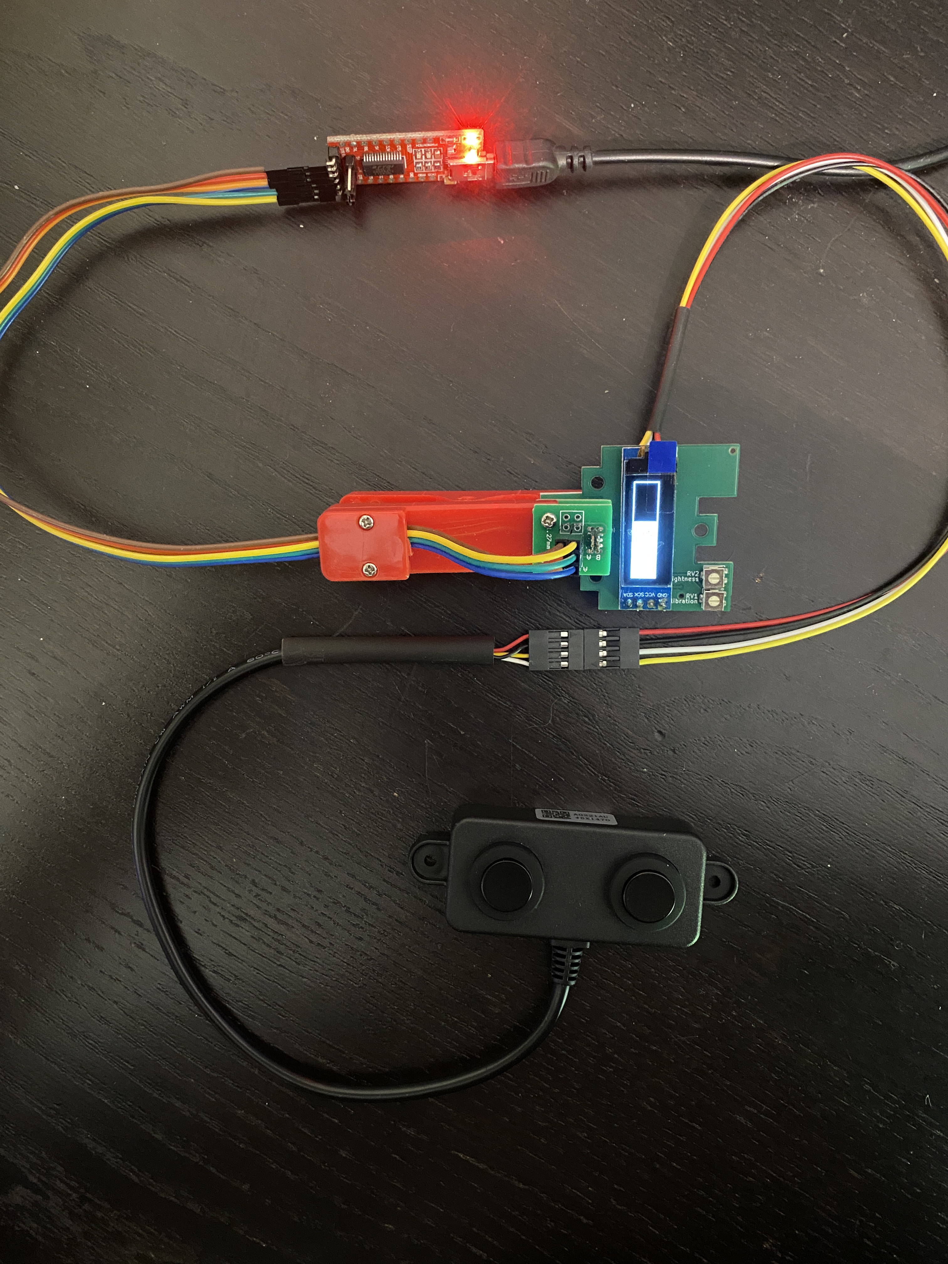
I encountered issues with measurements instability. As per the sensor's documentation:
(2) Communication instruction: When the pin (RX) is floating or set to high, the module outputs a processed value that is more stable, with a 100–500 ms response time. When the RX pin is set low, the module outputs a real-time value with a response time of about 100 ms.
So to stabilize the data, I forced the TX_PIN (connected to sensor RX, pin PD4) to stay low, enhancing stability.
Depending on how you consume the data stream, you can also experience tons of “garbage” (corrupted frames or incorrect readings). My approach took inspiration from DFRobot sample code plus additional insight from this comment.
My personal touch was a circular buffer to manage frame reading. This also offered a great opportunity to test PlatformIO’s unit testing framework.
2. Communication with SSD1304 OLED Display
I used the Adafruit_SSD1306 library to control the OLED display. This library integrates seamlessly with the display, you just have to focus on the GUI design and helper functions to display sensor readouts.
3. Communication with PTVO Firmware
For integration with PTVO firmware (Zigbee communication), I used the ptvo-data-tag-link library, making the board appear as an UART Sensor. The provided examples combined with library source code offers a comprehensive starting point.
4. Repurposing Board Potentiometers as a Display Trigger
I wanted to avoid the display to be constantly on. Easy problem to solve with a timer, except I did not anticipated the trigger button on my design to turn it on.
The only HMI hardware was the two potentiometers for brightness and calibration control. However, brightness adjustments on the OLED didn’t yield significant results (see this comment), and calibration could be managed remotely via Zigbee/PTVO (you can send values to your device through Zigbee).
My solution was to repurpose the potentiometer footprints on the PCB to accommodate a 4-leg push button. Specifically: I reused the brightness (A0/15 Arduino pin) and calibration's ground pin and left the remaining ones unconnected.
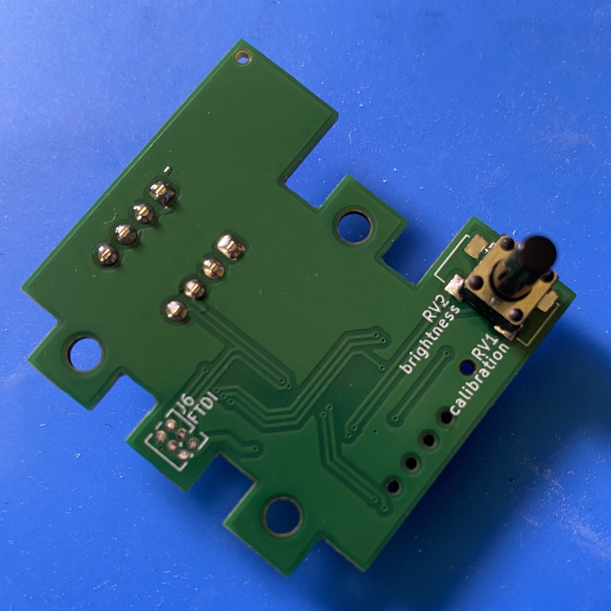
Hopefully these pins support Pin Change interrupts but require the ISR1 vector, which isn’t compatible with the SoftwareSerial library. To resolve this, I integrated the NeoSWSerial library for serial communication and the EnableInterrupt library to manage the interrupt handling effectively.
This configuration preserves both the functionality and responsiveness of the board while minimizing power consumption.
Project improvements
Below are some improvement ideas that I thought of throughout the project:
- I realized the potentiometers were unnecessary since I could send setting values via Zigbee. They can be permanently replaced by a push button.
- Regarding the push button:
- a long press on the button could bring up a debug screen to report eg. connectivity with the A02 sensor or the PTVO firmware
- a double press could force all values to be sent to PTVO firmware for debugging purposes
- PTVO firmware communication could be done via a separate (software) serial channel, preserving the UART for FTDI programming and debugging (as of today the two mixes in)
 Nicolas Colomer