 Eric Lind
So after my son finally soldered the stage 2 board I started testing it, like checking all power connections, all grounds and generally check for shorts. And of course I found out that I had made a big mistake!
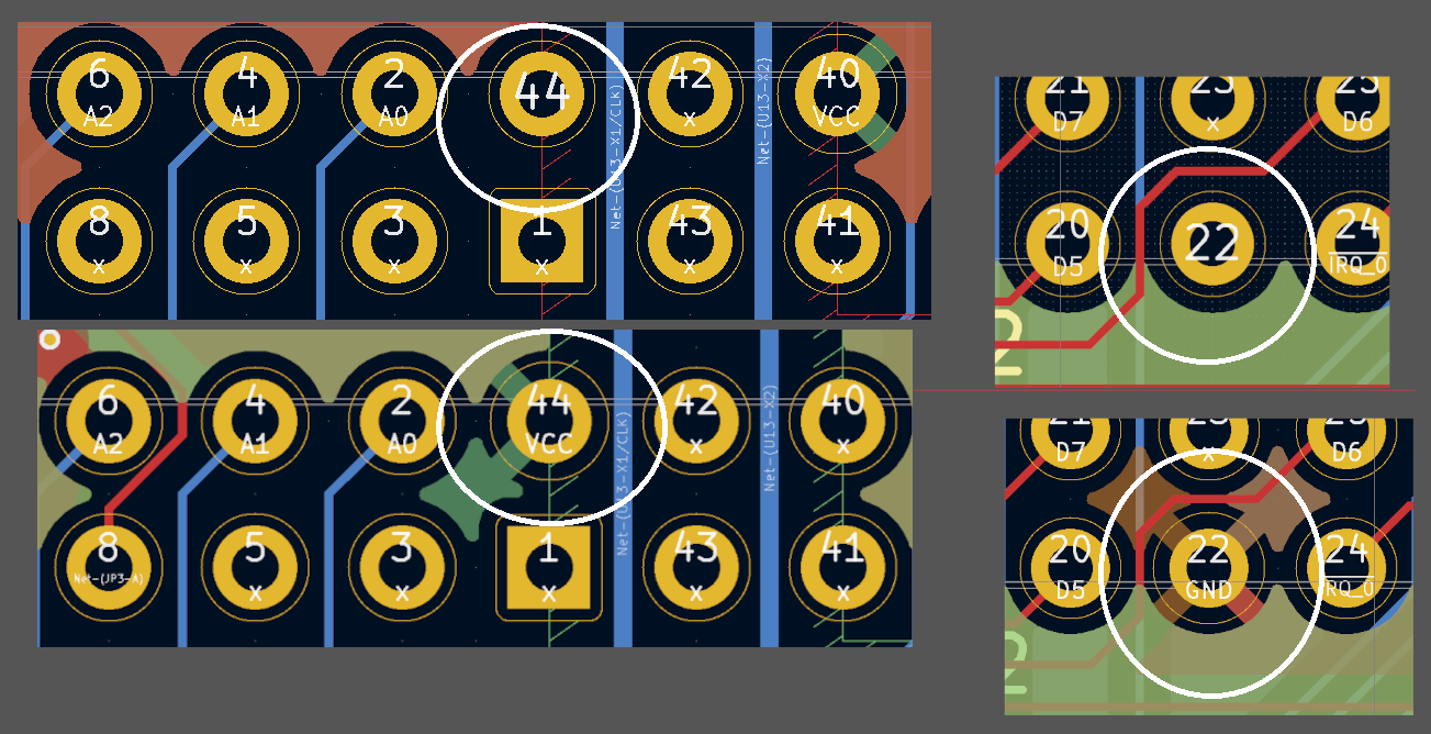
The power pin and ground pin on the serial controller is connected to wrong pins. And if you look in the schematics you can see that I made the symbol for it wrong.
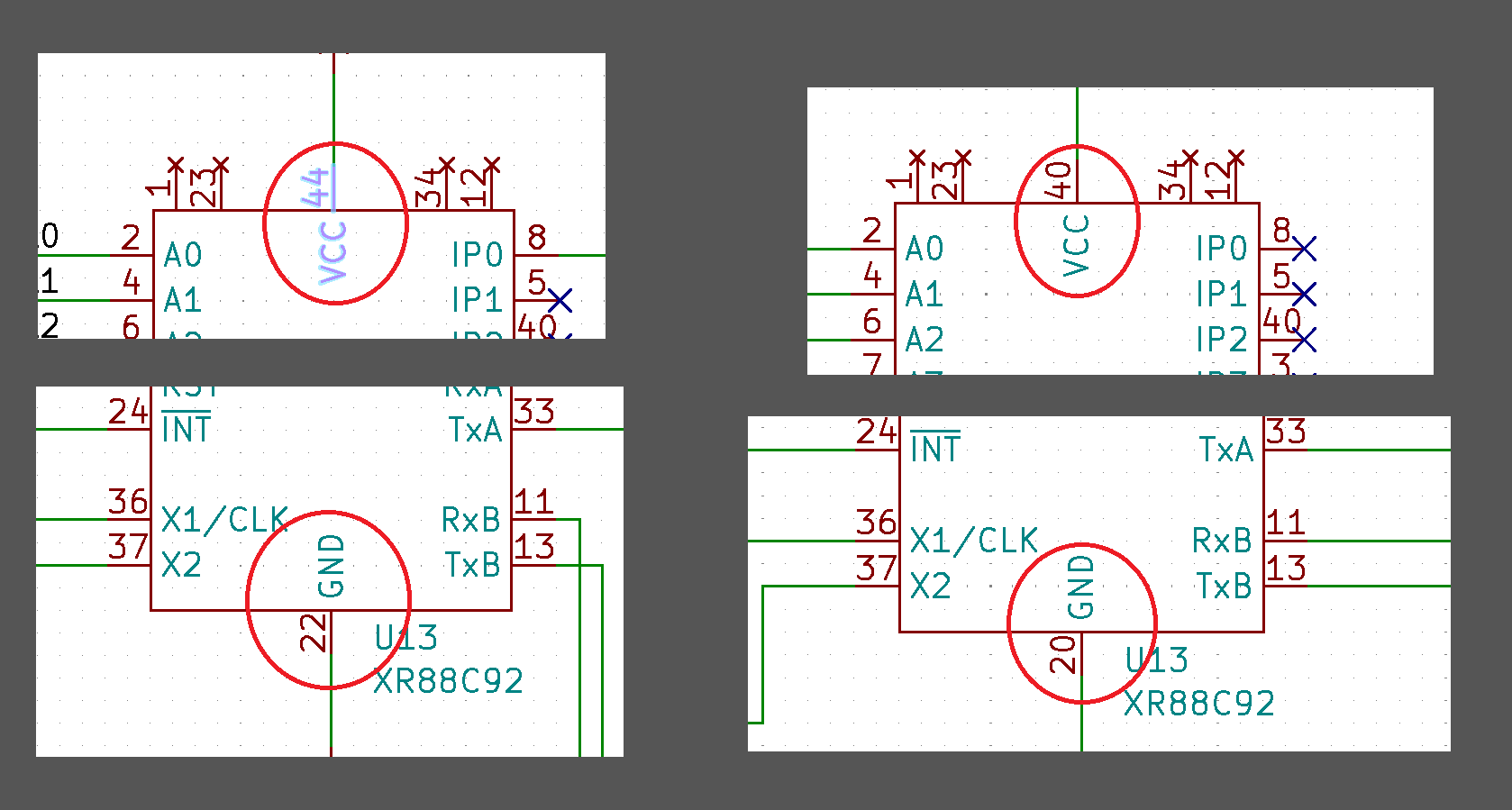
Fortunately can it be "re-wired" to work. I will just bridge pin 44 to VCC, pin 40 is an unused input pin so it does not matter. And the ground had not been filled on pin 20 so that will not be a problem to just bridge pin 22 to GND.
Crisis adverted!
I will continue to check connections before i populate the board and power it up. I have measured the voltage from the regulator and it is nicely holding on 5.0v. Soon it is Christmas Hollydays and I will be able to take more time to test this bord.
Discussions
Become a Hackaday.io Member
Create an account to leave a comment. Already have an account? Log In.