 Nguyễn Phương Duy
The old problems
The first CYOBrain design has several setbacks:
- The chip might run out of memory while running both the coding portal and other heavily demanded tasks (operating WiFi hotspot, running multiple sensors at the same time, reading music from a micro SD card, and playing through the built-in speaker, etc)
- Users do not know the battery level of the robot
- The extension block is too limited (2 GPIOs, 5V and 3.3V power supply, UART and I2C) → cannot connect SPI devices, especially external camera module
- The microphone is not running I2S → cannot record sound when running Python or Block
Design goal
- Fix all the listed problems
- Prepare for future expansion, including new add-on modules (wheelbase, camera module, more sensors, etc)
- Maintain the final cost increase of new CYOBrain under $15
Several requirements include:
- Users will be able to easily swap CYOBrain from CYOCrawler (legged robot) to other mechanical bases (robotic base with wheels, robotic arm, etc)
- Users can easily connect multiple external peripherals to the robot: sensors, camera, OLED display, LCD, etc
- Users can use the CYOBot coding portal for an extended amount of time without freezing/blocking
- Users can use CYOBrain for more complex projects: Voice-controlled applications, applications with camera, applications with media/audio player, applications with different types of motion and applications with multiple concurrent tasks, real-time applications
Proposed solution
- Use a stronger ESP32 chip: ESP32-S3 with built-in PSRAM (8MB) and 8MB flash. This is an x16 improvement from the previous chip. The previous frozen portal problem comes from an out-of-memory error. With this improvement, the robot can function for a long time without running out of memory. In addition, ESP32-S3 has more GPIOs to use, allowing connection to more external peripherals.
- Add in battery indicator/battery level circuit to be independent of the microcontroller, and will always be able to tell battery level every time the robot is turned on. Combine this battery indicator with the power LED, so that >= 30% is green and < 30% is red.
- Change the position of the power LED and charging LED to the side, allowing users to easily see the LEDs when the robot is turned on/when the robot is plugged in.
- Add SPI to the extension block (for LCD, OLED display, and camera connection).
- Add all unused GPIOs to the extension block.
- Change microphone to I2S interface, use 2 microphones instead of 1 for noise canceling and other audio-related applications.
- Add direct battery output to the extension block to use CYOBrain to power other external peripherals requiring large power consumption.
- Add 1 GPIO direct-controlled LED for curriculum support (basic GPIO activities - Blink)
- Wire out all 16 channels of PCA9685 for more connectivity.
- For each robot design, there will be a separate Mechanical Board to handle the required peripherals for controlling the corresponding mechanical movement, and necessary connectivity to connect with CYOBrain. This means that the current CYOCrawler design will be split into 2 parts: the head (CYOBrain) and the body (the hip with 4 legs). The Mechanical Board will be positioned inside the body, so that the head can easily be plugged into the body and start controlling the legs.
The proposed design change will add an estimate of $10 to the final cost of CYOBrain.
The Mechanical Board will hold all the extra peripherals needed so that:
- CYOBrain can easily control the mechanical movement of the robot using either UART, I2C, SPI, or GPIO.
- CYOBrain will power the mechanical board with the same battery.
- CYOBrain can easily attach to and detach from the Mechanical Board.
The additional Mechanical Board will add an estimate of $4 to the final cost of CYOCrawler (legged robot). The Mechanical Board of other future robotic bases will add more cost to the final robot depending on the additional required peripherals, for example:
- Robotic base with wheel will have H-bridge (motor driver) and DC motors.
- Camera module will have a camera and pan-tilt mechanical frame with servo motors
Solution
After a month, the new CYOBrain PCB is done, with the following reference:
1. The audio module follows ESP32-S3 Korvo 2 V3.0 (https://espressif-docs.readthedocs-hosted.com/projects/esp-adf/en/latest/design-guide/dev-boards/user-guide-esp32-s3-korvo-2.html) using ES7210 audio ADC chip and ES8311 audio CODEC chip for microphone and speaker respectively.
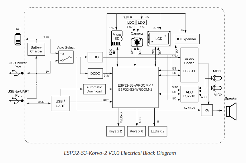
Luckily, the design comes with an extensive source code for audio (esp-adf - https://github.com/espressif/esp-adf) with MicroPython support.
2. All 16 channels of PCA9685 are wired out, but in a way that the first 12 channels are kept the same, so that there will be backward and forward compatibility, meaning that when we are done with the Mechanical Board design and decoupling of the brain and body (base) of robot designs, the old boards should be able to work (to some extend) as well.
3. SPI and power source are wired out to extension block, so that we can power the Mech Board later on, and as well connect things like the camera module (the Arducam that uses SPI and I2C):

4. Battery level indicator and charging indicator are added in.
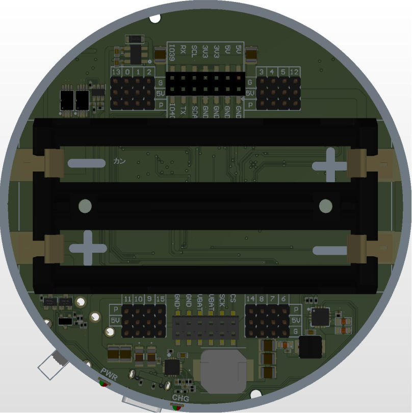
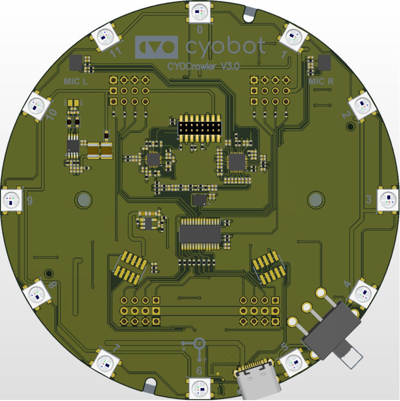
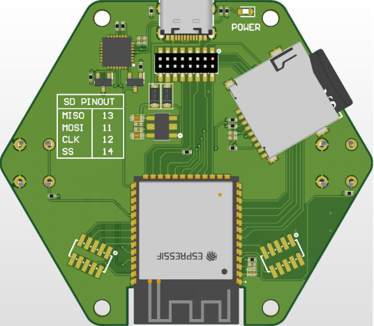
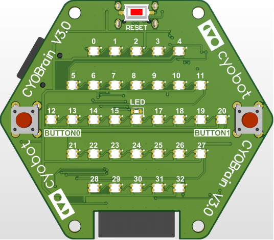
The most up-to-dated board looks like this:
Discussions
Become a Hackaday.io Member
Create an account to leave a comment. Already have an account? Log In.