I started by considering various sensing technologies. Switch mats are a bit expensive and would require me to pull up carpeting for installation. Radar and sonar sensors work relatively well for automatic doors but aren't great for pinpoint detection in a confined area. Beam break optical sensors work very well but require wires on both walls. I decided to try a retro-reflective optical sensor because it seemed likely to be reasonably reliable, inexpensive and easy to install. Most optical sensors I've seen use infrared but I worked on a project a few years ago which called for infrared illumination for a video camera and learned that the protective mechanisms built into our bodies to protect our eyes from excessively bright light don't work with infrared so you have to be very careful to limit the brightness of any infrared light which might shine into a living being's eyes. Because of this, I decided to try to use visible light for my sensor.
For this lap counter I defined a lap as walking from the top of the stairs to the bottom of the stairs and then back up to the top of the stairs. I initially considered counting laps by placing a sensor at the middle of the stairs and dividing the number of times the sensor detects me by two (one for down and one for up). Unfortunately, the human body is not fully convex and continuously changes shape while walking so my optical sensor would probably sense me multiple times each time I passed it. I thought I could remedy the situation using techniques similar to debouncing of mechanical switches but thinking about that reminded me of the bounceless switch circuits from the book Engineer's Notebook A Handbook of Integrated Circuit Applications by Forrest M. Mims, III (copyright 1979 by Radio Shack).
All of the bounceless switch circuits in the book use SPDT switches wired to RS latches so that one switch contact activates the Reset input and the other switch contact activates the Set input.
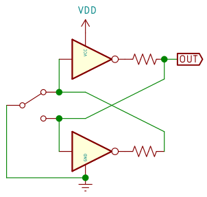
I decided that I could replace the SPDT switch with a pair of optical sensors (one at the top of the stairs and one at the bottom). I then considered that the LEDs for the sensors would probably be the highest power draw in the entire system so it would be nice to have only one of them on at a time. I drew a schematic for a circuit which would use the outputs of the RS latch to control the sensor LEDs and it looked a bit complicated so I tried to figure out a way to simplify it. After about an hour and a half of figuring, I went to bed. Just as I was about to go to sleep, a much simpler circuit occurred to me. I tried following the logic through mentally but quickly realized I was too tired to think straight so I went to sleep.
The next morning, I drew the schematic for the circuit and convinced myself it would work.
I wired a miniature version on a breadboard using photo-interrupter modules I had on hand. The photo-interrupter modules were IR so I wired some visible LEDs in series with the IR LEDs in the photo-interrupter modules to provide visual feedback. I tested the circuit and it worked as expected. I don't know if anyone else has devised and named this circuit but, in case no one has, I call it a bounceless optical switch.
I don't think any exercise program will make me thin enough to fit through the gap in the photo-interrupter modules so the next step is to acquire or make retro-reflective optical sensors.
I searched for existing sensors. I found several which would work at up to 10cm for reasonable prices. I found several which would work at 6m and even longer distances for non-reasonable prices. I did not find any which used visible light so I decided to make my own retro-reflective optical sensors.
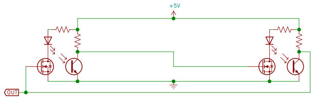
I searched for high output visible LEDs with narrow view angles and selected the Vishay VLCS5830 because it had the narrowest view angle (8°) I could find. I prefer surface mount components but could not find any with that narrow a view angle. I then searched for a matching phototransistor and selected the Everlight ALS-PT204-6C/L177 because it's peak sensitivity wavelength (630nm) was very close to the wavelength (624nm) of the LED. I selected a 2N7000 MOSFET in the TO-92 package for switching the LEDs. Finally, I searched for a corner cube array retro-reflector and found the Benner Engineering BRT-1. Since all of the electronic components were through-hole components, I decided to use the Adafruit Perma-Proto Small Mint Size PCB for assembling the sensors.
Once I received my parts, I tested one of the LEDs and found that it was extremely bright and really did have an 8° view angle. I also found that it bled a significant amount of light to the sides and even to the rear so I would need a shroud to prevent the LED from activating the phototransistor continuously and to keep from blinding myself if I glanced in the direction of the sensors. I machined backplates for two of the LEDs from black plastic and shrouds for the LEDs (which pressed in place onto the back plates) out of aluminum. I machined an adjustable shroud for the phototransistor out of black plastic.
I taped the retro-reflector to the wall of the staircase and set up the two shrouded LEDs and the shrouded phototransistor on a breadboard which I set up on the stair railing across from the retro-reflector. I powered the set up with 5V from a bench power supply. I measured the voltage drop across the phototransistor which was in series with a 10KΩ resistor. The voltage drop was 4.42 with the phototransistor unobstructed and 4.46 with my hand between the phototransistor and the retro-reflector. If I put my hand close to the phototransistor, the voltage dropped to 4.38 which showed that my hand could reflect more light at close range than I was getting from the retro-reflector. This was nowhere near enough difference to be useful.
I ordered two different types of LED laser collimating lenses to try to narrow the beam from the LEDs and to try to capture more of the light for the phototransistor. I made a new shroud for the phototransistor with a provision for holding the lenses and modified the existing LED shrouds for holding lenses. I was not terribly surprised to find that neither of the lenses worked for narrowing the LED beams (although I was a bit surprised at how badly they worked). I was slightly more surprised to find that neither of the lenses helped with the phototransistor at all. Based on the lens tests, I realized I really didn't understand the optical process with which I was trying to work so I set out to learn about it.
I used FreeCAD to sketch a 2D ray trace of a point light source and a coarse corner reflector array.
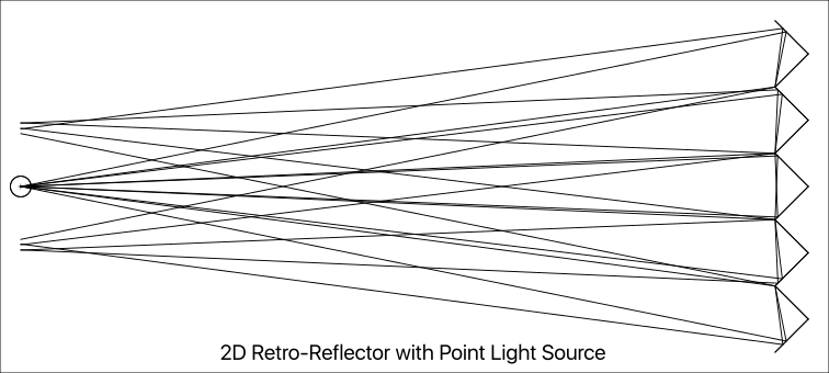
From this ray trace, I realized something I should have realized from the beginning: A diverging beam striking a corner reflector gets re-converged. I would say it gets focused but it really doesn't because it also gets spread laterally by a little less than twice the width of one of the corner cells. A corner cube retro-reflector works the same way as a corner reflector but in three dimensions. This is why the lenses did not help with the phototransistor; the light was already converging when it reached the lens so there really wasn't anything for the lens to do. This ray trace also highlighted that the sensor should be less than one corner cube cell width from the LED; fortunately, mine already were.
The LEDs were projecting a spot about 140mm wide on the wall and the retro-reflector was only 24mm in diameter so a lot of light was being wasted. I searched for larger retro-reflectors and finally found some 76mm diameter units (TELEMECANIQUE SENSORS part number RF30) at Grainger so I ordered a pair. With a 76mm retro-reflector the same breadboard set up I tested previously now produced a 0.24V drop unobstructed and a 4.46 drop when obstructed by my hand. This difference was easily large enough to work with so I started to plan the assembly of my sensors.
I used FreeCAD to model the sensor board layout. I determined that I only needed half of one of the Perma-Proto boards for each sensor so I cut one in half and used my mill to machine the ends smooth. I decided to use some wall anchors with #6 screws to mount the sensors to the wall so I used my mill to cut one mounting hole in each of the two half boards. I was concerned the plastic backplates I used for testing would melt when soldering the components to the PCB so I machined a combined backplate (single backplate with holes for two LEDs and one phototransistor) for each sensor out of some black FR4 I had left over from a previous project. I machined combined LED/phototransistor shrouds from black plastic. I then assembled one of the sensor boards and a short cable. I tested the assembled sensor and it worked just as well as the breadboard version had so I assembled and tested the other sensor board.
Once I had two working sensor boards, I installed them on the wall and installed the retro-reflectors on the opposite wall. (My decision to use visible light made the process of aiming the LEDs and positioning the retro-reflectors much easier than it would have been with IR.) I then braided the wires for the main connecting cable and installed connectors on the ends. I zip tied the cable to the hand rail supports and connected it to the two sensors. I then used the short cable I made previously to test the bounceless optical switch and it worked just as the breadboard version had.
Eventually, I plan to connect my bounceless optical switch to an M5Paper but for now I am using it with a breadboarded counting circuit with a pair of 7-segment LED displays I purchased at Radio Shack over forty years ago.