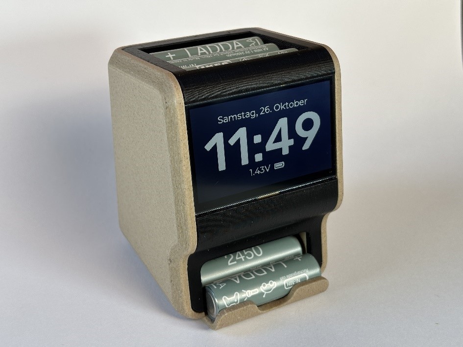
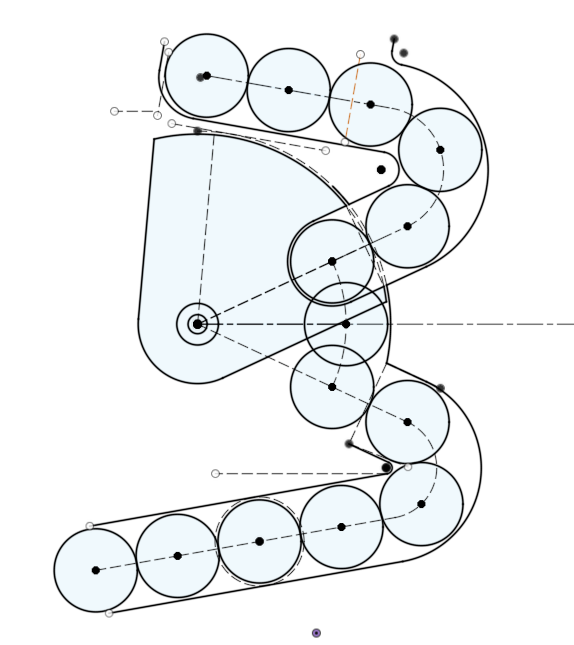
SPINC is supposed to always sit on your desk and serve as a charger, battery storage and a clock. For that, the design had to be as compact as possible and look good in its office environment. I started out with a 2D sketch of the autoloader mechanism, to see how much space was needed. With this setup, the top and bottom chutes each fit six batteries, which seemed like a sensible amount. Between the cutes, the rotating arm is mounted that can move a battery between three positions: Up to load in batteries, middle to charge, and to the bottom for ejecting the cells. In its lower position, the arm also has to block the input chute.
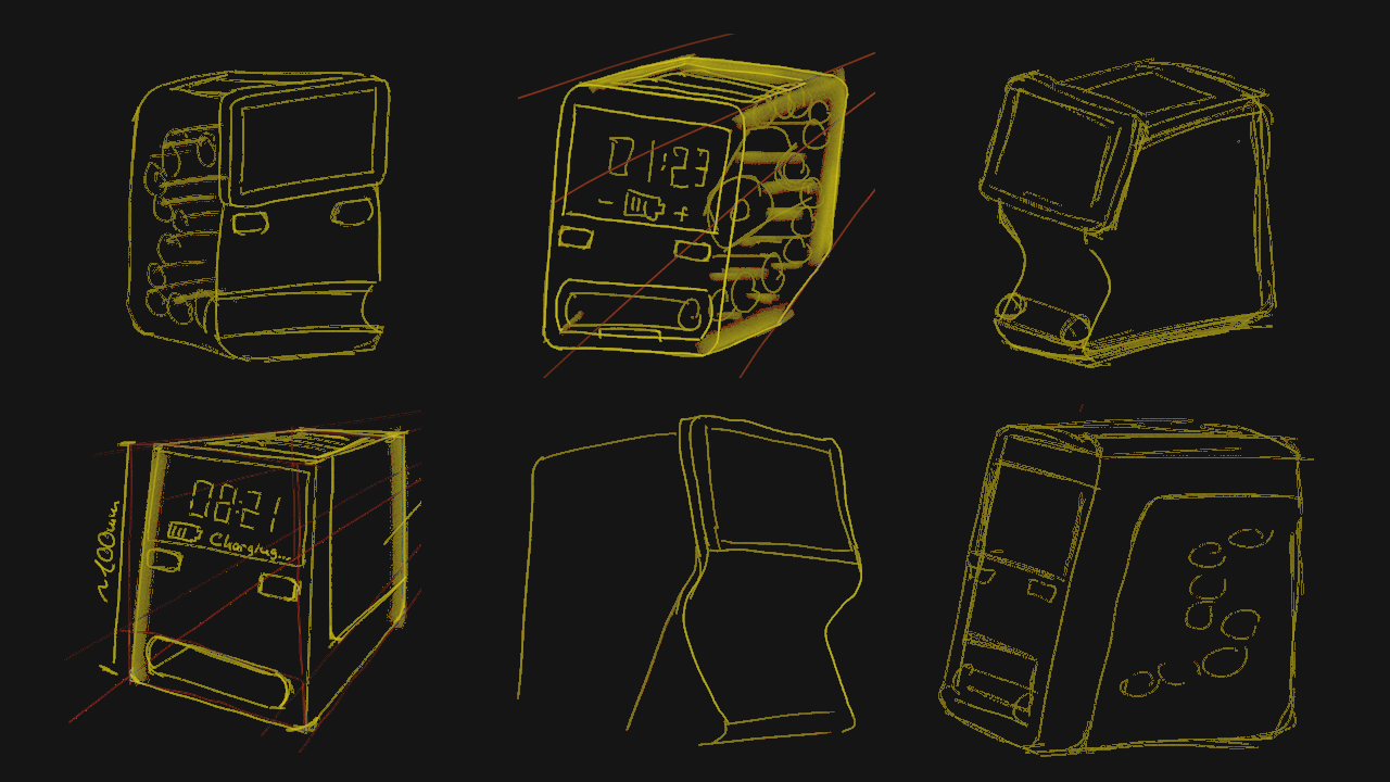
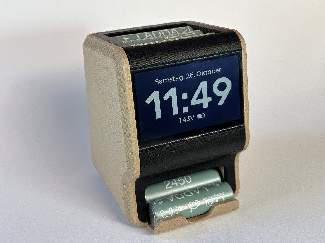
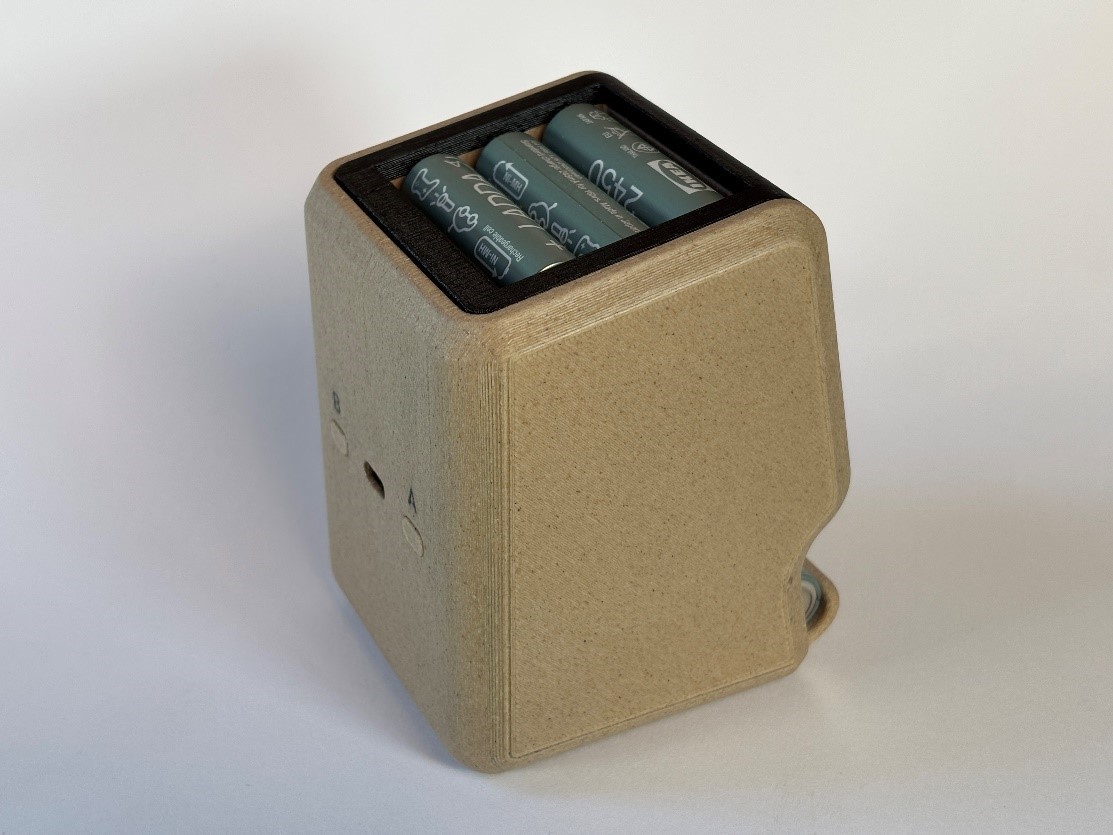
The next step was finding a nice enclosure geometry to fit around this mechanism. It needed an opening on top for dumping in empty batteries and a second opening to pick up the charged cells. I also wanted to have the 2.7” Sharp LCD (LS027B7DH01A) on the front to display the charging status and a clock. And finally, a PCB had to fit somewhere in between. With my previous projects, I took inspiration from retro tech or similar existing products. But since this is a very unusual device, it was difficult to come up with a design that was both appealing and functional. I did lots of sketches and even printed a mockup.
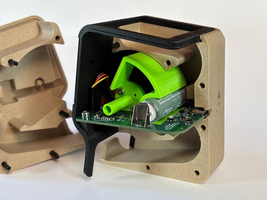
The final design consists of three main pieces: Two halves form the main body of the charger. The input and output chutes for the batteries are also defined by these halves. The third part covers the front and top of the charger. It holds the display and circuit board. What is neat about this design is that only a single PCB is needed for all the various function. It is just in the right spot to contain the battery terminals, the USB port, pushbuttons and the display connector. And the PCB even has one more purpose: The charger needs to know if a battery was inserted, or else it has to constantly rotate the arm up and down. This is done by having an optical proximity sensor on the PCB, pointing at the input chute.
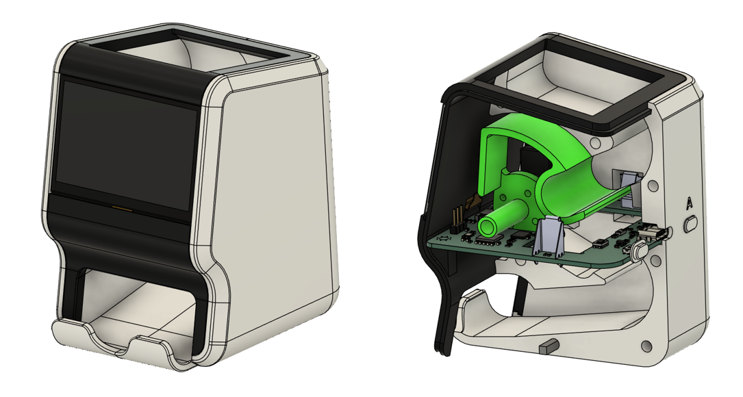
Apart from the three enclosure parts, there is also the arm that moves the batteries. With one side connected to an EMAX ES08A micro servo and the opposite side suspended in the right enclosure half, it is very securely held in place.
For most of my previous projects, I designed the enclosures to be printed with the inside facing the print bed. This makes for a nice outer surface, but requires lots of supports. It turned out that the rough surface that is left after removing the support, leads to batteries getting jammed in the sloped chutes. Instead, I had to print the halves with the outside facing the print bed. I used matte black PETG filament from Colorfabb for the front cover and wood PLA from Black Forest Filaments for the main body. I think this way, the device fits in nicely on a desk.
 Max.K
Max.K
Discussions
Become a Hackaday.io Member
Create an account to leave a comment. Already have an account? Log In.