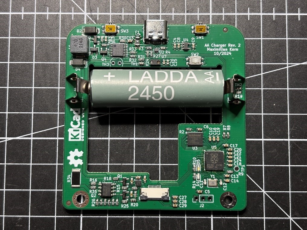
Based on the mechanical design, I already knew how the PCB had to be shaped and how much space was left to fit the electronics. And these electronics had to fulfill a number of features: Charge the battery, drive the display and interact with sensors, buttons as well as the servo motor. The charging would have to be quick, since the device can only charge one battery at a time. And because batteries are just thrown into the top of the device, it would have to work with any polarity. This is quite an unusual requirement for a charger, as they usually have mechanically coded terminals and will simply not work with the polarity swapped.
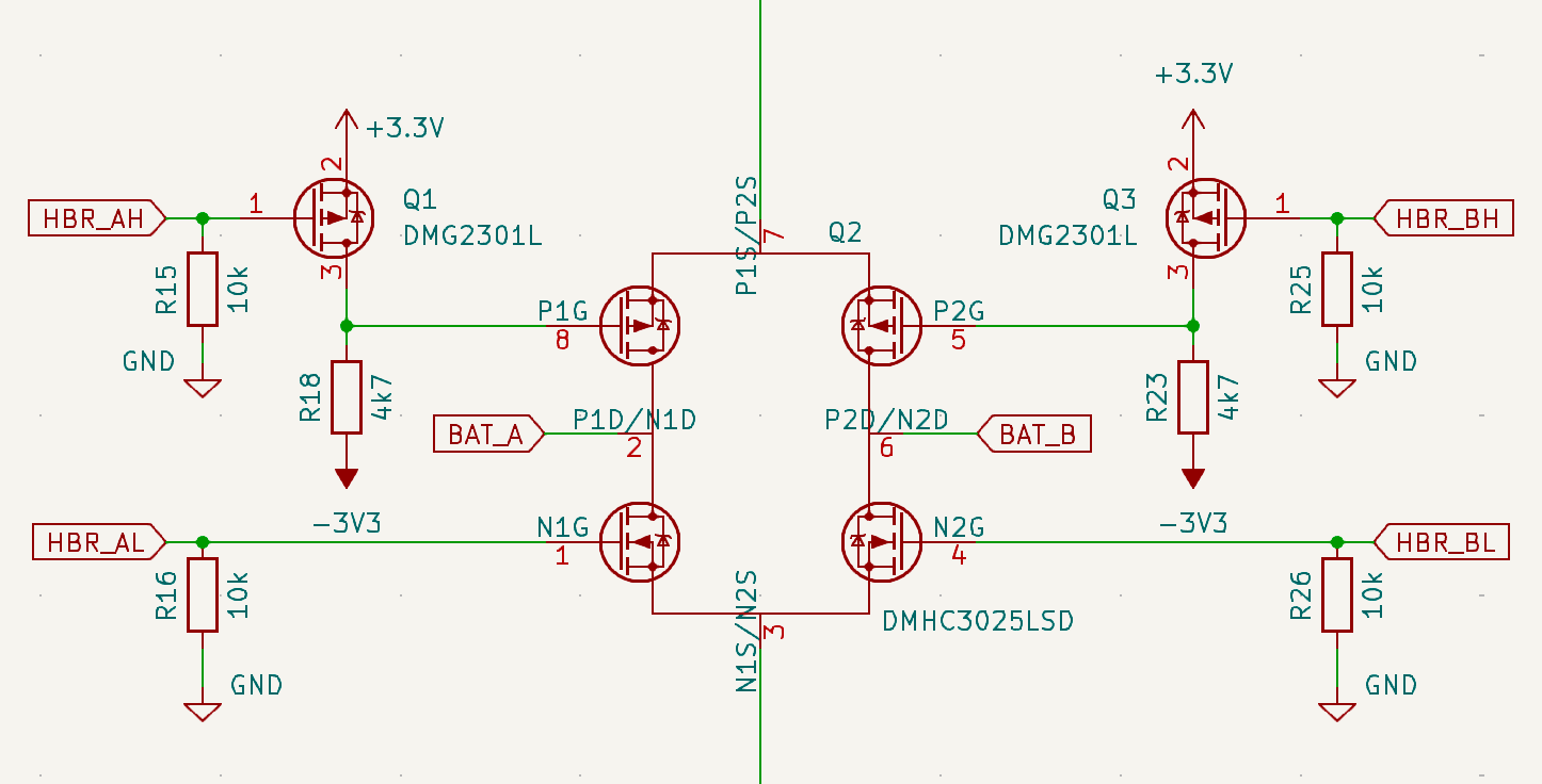
I decided to start with the seemingly trickiest part - the polarity inversion. The usual solution for changing the polarity of something like a DC motor is an H-bridge. An H-bridge consists of four switches arranged in an H-shape, with the load in the middle. Depending on what switches are closed, the voltage at the load can be reversed. You could use relays as switches and operate them with a microcontroller. But with the limited space on the board, that is not practical. Instead, I went with an H-bridge IC (DMHC3025LSD). It is actually intended for DC motor control but in the end it’s just two p-channel and two n-channel MOSFETs in an SO-8 package. Instead of the supply voltage for the motor the charging circuit will be hooked up to the H-bridge and instead of the motor as a load it will be a battery. But there was one problem to figure out. At the top of the H-bridge, which controls the positive supply voltage to the battery, the two p-MOSFETs will only have a very low source voltage of around 1V. The MOSFETs will turn on when their gate-source (VGS) reaches are a threshold between -1V to -2V. But when the gate cannot go lower than 0V, the VGS might not be enough to fully turn the MOSFET on. This leads to increased resistance and losses, which could interfere with the charging. My solution to this was to simply drive the p-MOSFETs with a negative voltage. How do you get a negative voltage? I found the LM27761, which is a tiny switched-capacitor voltage inverter, that needs only minimal components to invert the 3.3V supply voltage. Another set of MOSFETs makes it possible for a microcontroller to switch the H-bridge gates between +3.3V and -3.3V.
I tested this in LT-Spice first, which seemed promising. On the final PCB the voltage inversion circuit worked out perfectly as well. It might still be an overcomplicated solution, so I would love to hear in what other ways this could be solved.

To determine which way the battery was inserted, the two contacts in the middle of the H-bridge are monitored by ADC inputs of the microcontroller. A simple voltage divider shifts the voltage up, so the input pins cannot get damaged by the negative voltage. With this setup, the microcontroller first checks in which orientation the battery was inserted. Then it can configure the H-bridge to connect the battery and the charging circuit in the right way.

Next, I needed to find a NiMH charging controller. I briefly considered building on myself, but that seems like a major project in itself. Unlike Lithium-Ion batteries where the charging just requires a constant current and voltage, NiMH cells are actually more difficult to charge. The difficult part is determining when the charging is finished, as NiMH batteries do not have a linear voltage curve. Fast chargers do this by detecting when the battery voltage slightly dips at the end of the charging process. If you miss this moment, the cells get overcharged and potentially damaged. As a safety feature most chargers also monitor temperature and charge time. The only other way of charging is trickle charging. NiMH cells will allow a certain continuous charging current where they do not overheat when overcharged. But this means charging for many hours, which is not ideal for a sequential battery charger. My first candidate for an integrated charger was the TI BQ25172. On paper it can charge 1-6 cells at up to 800mA. The problem is that it is a linear charger, so much like a linear regulator it reduces the input voltage of 3.3V to the cell voltage by converting the excess into heat. And doing so with a 2x2mm sized IC is not a good idea. Instead, I decided to use the MAXIM DS2712, which is a switch-mode charger. There is an ancient application note (https://pdfserv.maximintegrated.com/en/an/AN3607.pdf) detailing how to use the IC for USB-powered charging, which was exactly what I needed. On my board, the DS2712 is set to fast-charge at roughly 1A. But the current can easily be reduced by changing the value of the shunt resistor (R34).
While the charging process is monitored by the MAX2712, a microcontroller is still necessary for many other functions on the PCB. Since it came out, I always wanted to try working with Raspberry Pi’s microcontroller, the RP2040. Unfortunately, low-power designs are not its strong suit with around 400uA of current draw in sleep mode. Because of that I always went back to the ESP32. Without the need for low current consumption and no wireless features, this project finally fits the RP2040.

The other electrical components do not need much explanation. There is a display connector for the Sharp memory-in-pixel display. This display is directly powered by 5V from the USB port and controlled via SPI. The optical proximity sensor for checking if batteries are put into the device is connected to the RP2040 over I2C. And unlike the ESP32, the Raspberry Pi microcontroller has an integrated USB peripheral for programming, so no USB to serial bridge is necessary. In the end, all of the components fit nicely on the weirdly shaped PCB.

 Max.K
Max.K
Discussions
Become a Hackaday.io Member
Create an account to leave a comment. Already have an account? Log In.