PCB
I tried to build a 2-layer PCB, and I finally succeeded - although a 4-layer PCB probably would have worked better. You can see the layout here (updated version):
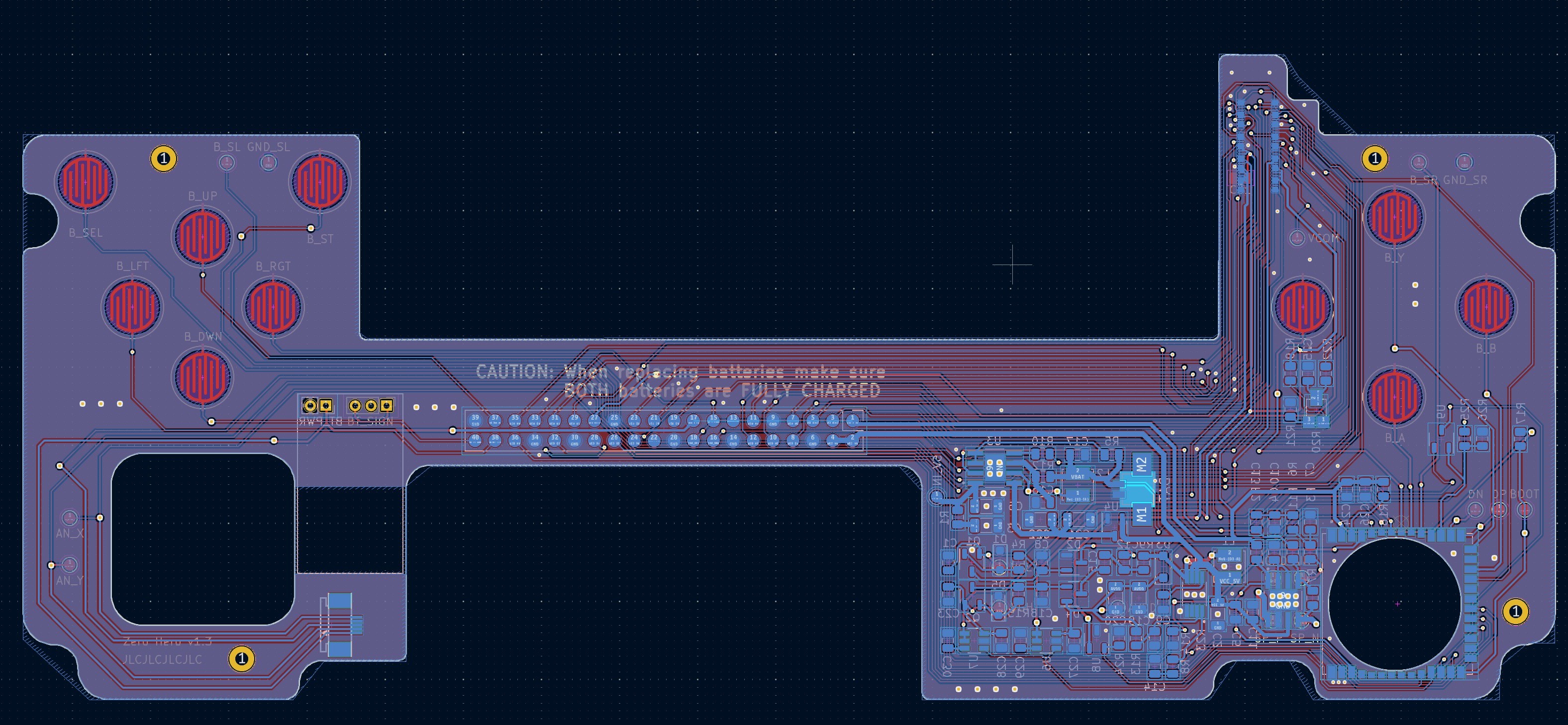
And that's the mainboard fully assembled (all components are on one side):

Display

The whole project was centered around the display of the HTC Athena which I had lying around for some time now but was unable to throw away. A blast from the past. I thought it would be perfect for a retro gaming machine, because:
* the diagonal size of 5" is (in my opinion) somewhat the sweetspot for a 4:3 VGA display
* the physical resolution is 480 by 640 pixels
* it's a TN display with an vertical design but the polarizer is orientated horizontally, so no weird color shifts when in landscape mode
* the vertical design with the IC mounted on the side of the display made it possible to achieve very small bezels on top and below the display.
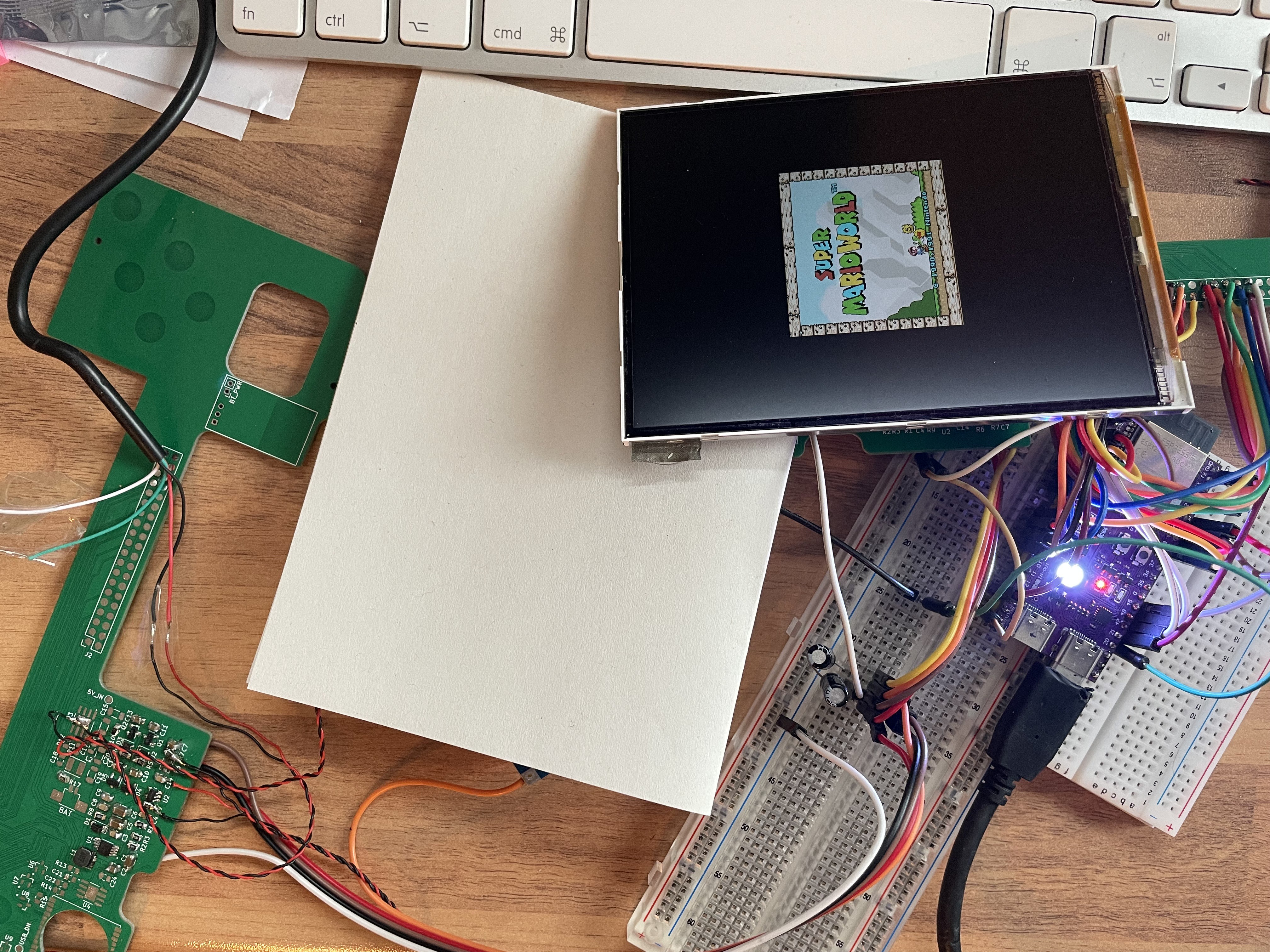
As I mentioned before: I started out with the display lying around. When I first started the project, I really underestimated the variety of different voltages these old display need. These are: VGL (-8.0 V), VGH (16.0 V), AVDD (+8.0V), VCOM (3.0V), DVDD (3.3V). You need to tightly stick to those values or otherwise the image quality will be impaired. Worse still, those voltages need to be applied in a strict order and timing or the LCD could be damaged. Fortunately, TI had an older switching regulator with a reference design close to the specs I needed. And of course you still need yet another supply voltage to power the backlight…
As you can see that the LCD power circuitry occupies a lot of the space on the PCB.

Housing
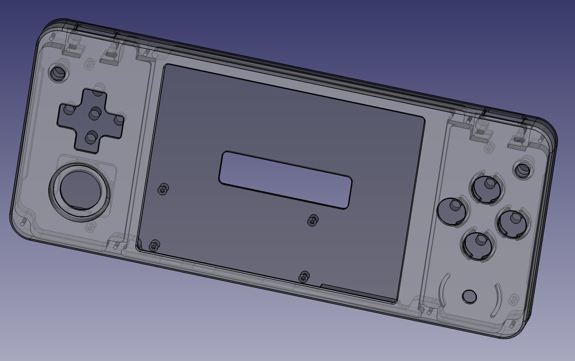
I designed the housing to be CNC machined with a wall thickness of 1mm. JLCPCB did a great job producing it (not affiliated).
Power
Fortunately, the Raspberry Pi Zero needs an input voltage of 5 volts and there are some inexpensive ICs that can both boost a LiPo’s voltage to 5 V as well as mange the charging of the battery. So that came in handy.
The PMIC is powered on by pressing a button. A transistor then isolates the button from the PMIC so that the button can be used as a regular input while the handheld is powered on – saving the need for a dedicated power button.
LCD interface
The LCD is driven via a 16-bit DPI interface – which means that a lot of traces had to be routed. Worst of all, the connector has a 0.3 mm pitch, which was not only a nightmare to hand solder, but also quite difficult to route (keep in mind the display is driven at approx. 30 MHz). There were several moments where I almost started from scratch, but I had challenged myself to get the routing done with a two layer board… Don’t believe me? See the pictures… :)
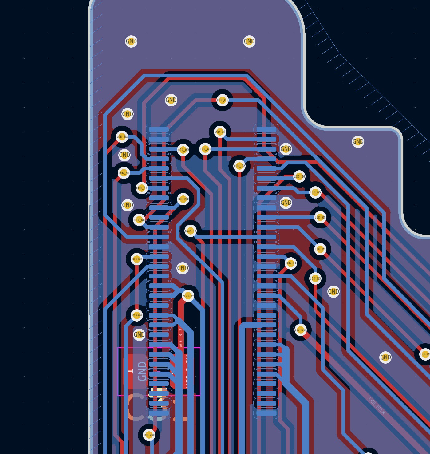
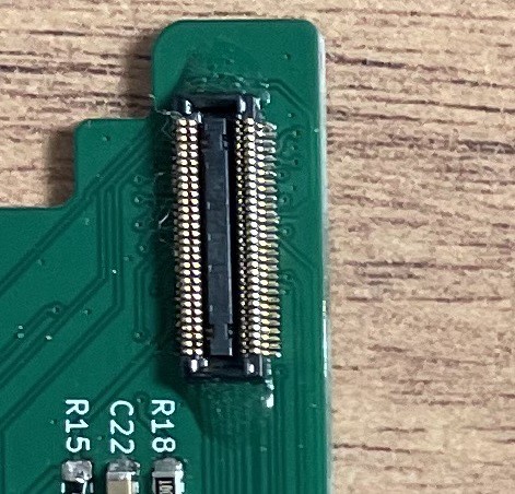
In the end I was able to successfully route all traces and when testing with an ESP32 I got a stable signal. No signs of signal degradation at specified clock speed (*phew*).
I/O
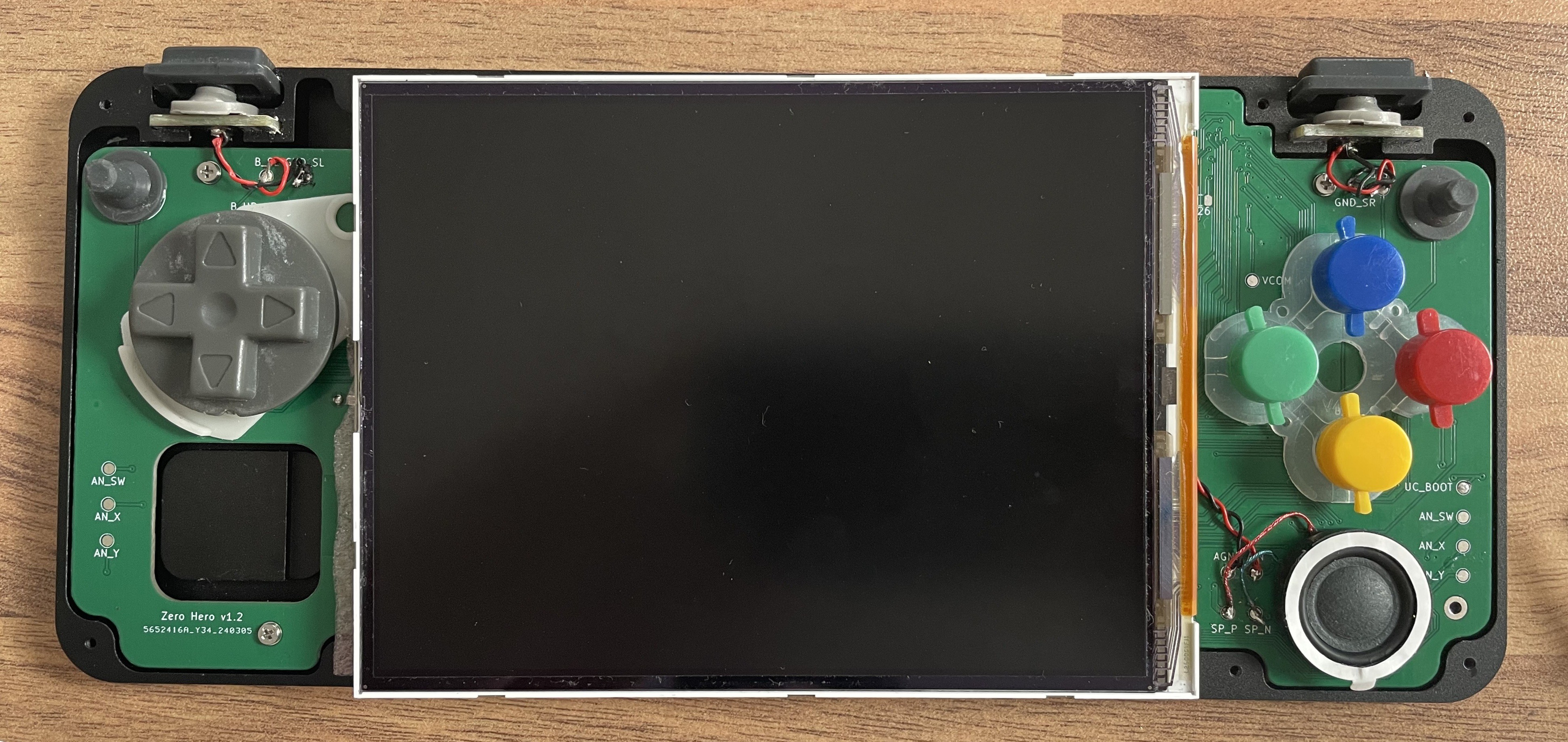
The handheld essentially features the SNES button layout: A, B, X, Y, L, R, Start, Select and a D-pad. There is also an analog input (PSP 1000).
Since I used up almost all GPIOs with driving the display. I opted for an ESP32-S3 as “coprocessor” (yeah, a little bit of an overkill).
The ESP32 captures all user inputs and also manages applying the LCD voltages, brightness levels and governs the power subsystem.
There is a hole under the ESP32 for the bottom part of a speaker – yeah, I got pretty space constrained as I wanted to keep the height at 12mm.
There is a USB port and an HDMI output (though I don’t really see the point of having that on a handheld).
Sound
Sound is output via an integrated Bluetooth speaker. However, I wish I had gone for an I2S solution. Because the output lags quite a bit (at least when using Retro Pi). Also, the amplifier’s filter are definitely in need of improvement as the sound output is more on the noisy side.
Bottom line
This gives a nicely working gaming handheld with the extra portion of retro. However, I would definitely go for a four layer board next time and drop the Bluetooth audio. I would also go with a Nintendo- Switch analog stick and shoulder buttons that “go around the corners”.
If you've made this far - thanks for reading and I hope you enjoyed :)
 fcipaq