Introduction
After an extensive search for a suitable off-the-shelf enclosure, I decided to design and 3D print a custom enclosure for my Catchcam project. My requirements were specific: a small and easy-to-assemble enclosure. I wanted to avoid the hassle of modifying a generic enclosure by drilling holes and cutting openings. By designing my own enclosure, I could ensure a perfect fit for my project’s needs.
Note: If you’re interested, you can pre-order a sample at vnucec.ivan@gmail.com.
Design Inspiration
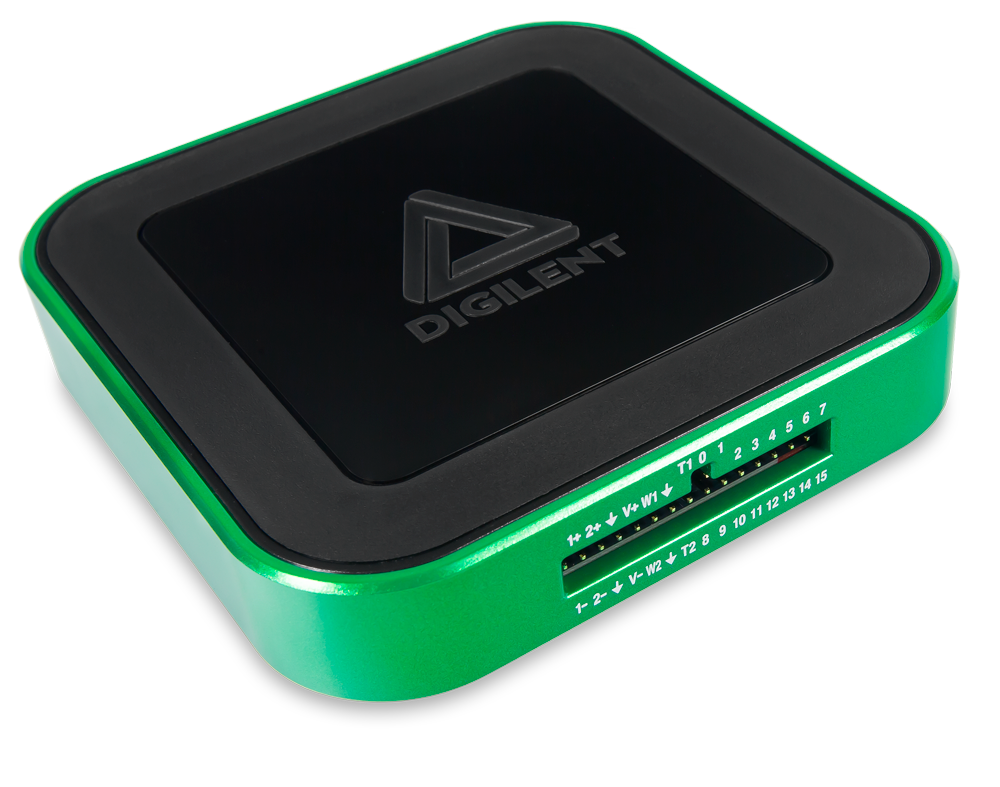
The main inspiration for the enclosure design came from the Digilent Analog Discovery 3 device. I really liked the look and feel of that enclosure, especially the rounded edges and the overall simplicity of the design. I’ve decided to go with a similar design for my Catchcam project.
Design Process
The enclosure is designed in FreeCAD which is a free and open-source parametric 3D CAD software. It took me a while to get used to the software, but I’m quite happy with the results. Although I have some experience with CATIA, I’ve decided to go with FreeCAD because it’s free and open-source. The journey was quite challenging because FreeCAD has a few quirks and you need to get used to the way it works. Also, FreeCAD was crashing quite often without any warning, so I had to save my work every time I’ve made some significant changes. Actually, the main frustration was that they had published a first major release v1.0 which implies that the software is stable, but it’s far from it. I’ve also tried OpenSCAD which is a script-based 3D CAD software because I love the idea that you can create 3D models using code, however, for complex shapes like the enclosure, the OpenSCAD code would be too complex to manage.
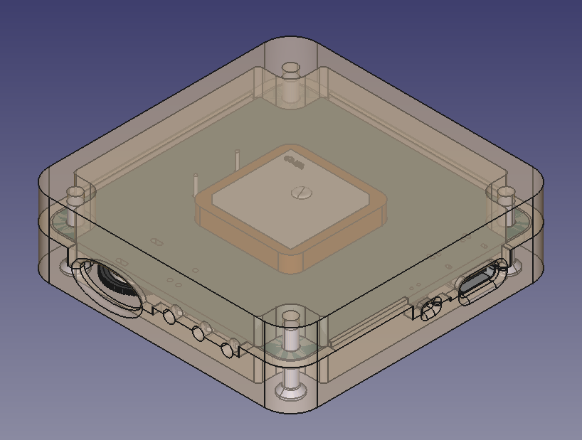
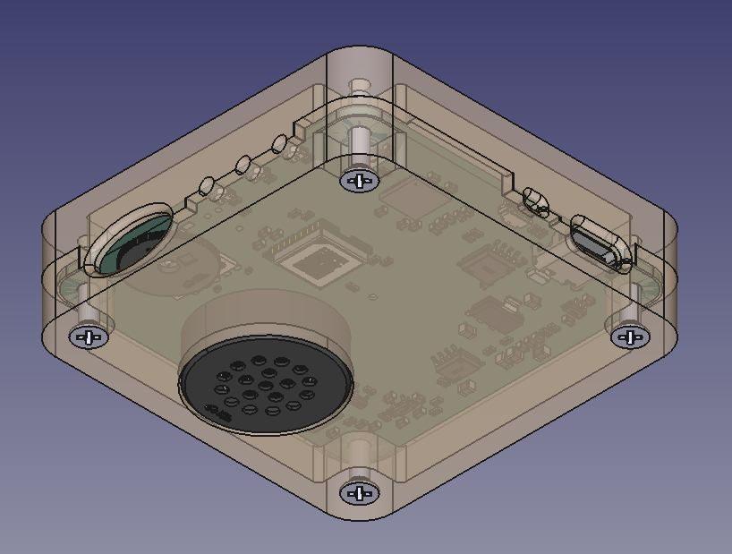
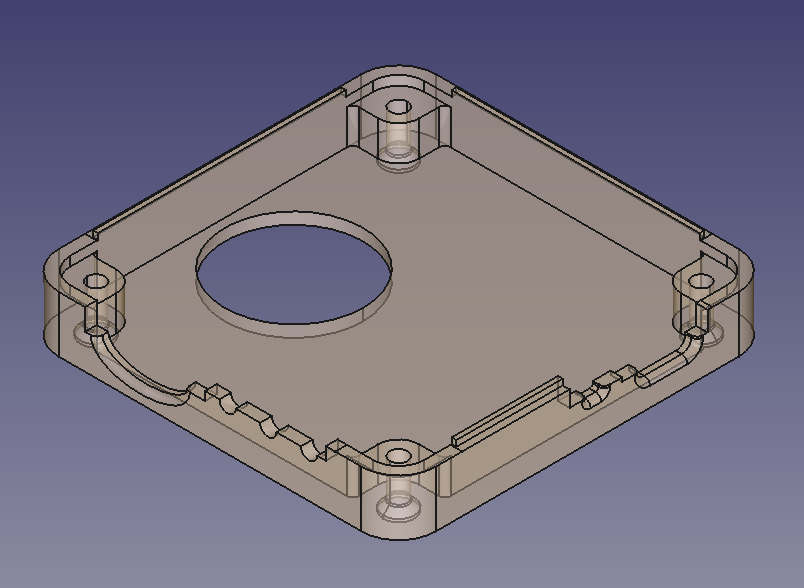
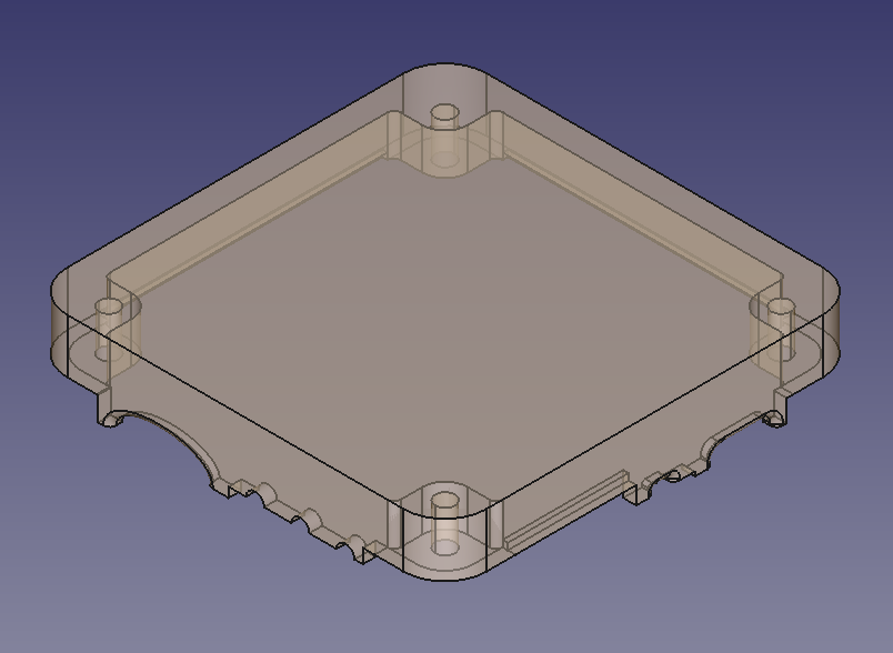
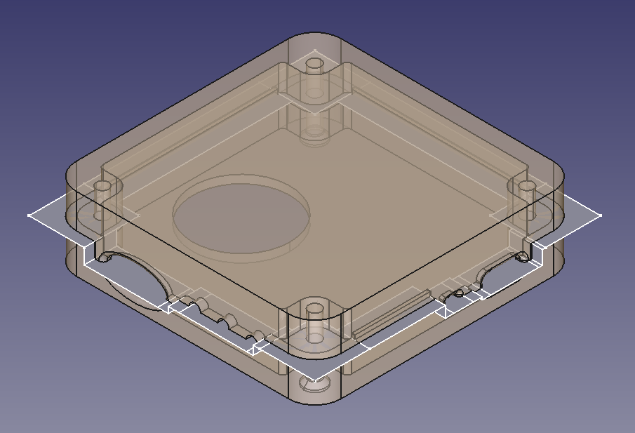
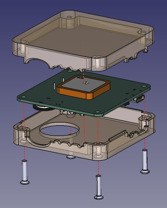
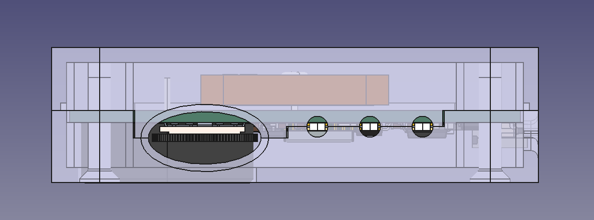
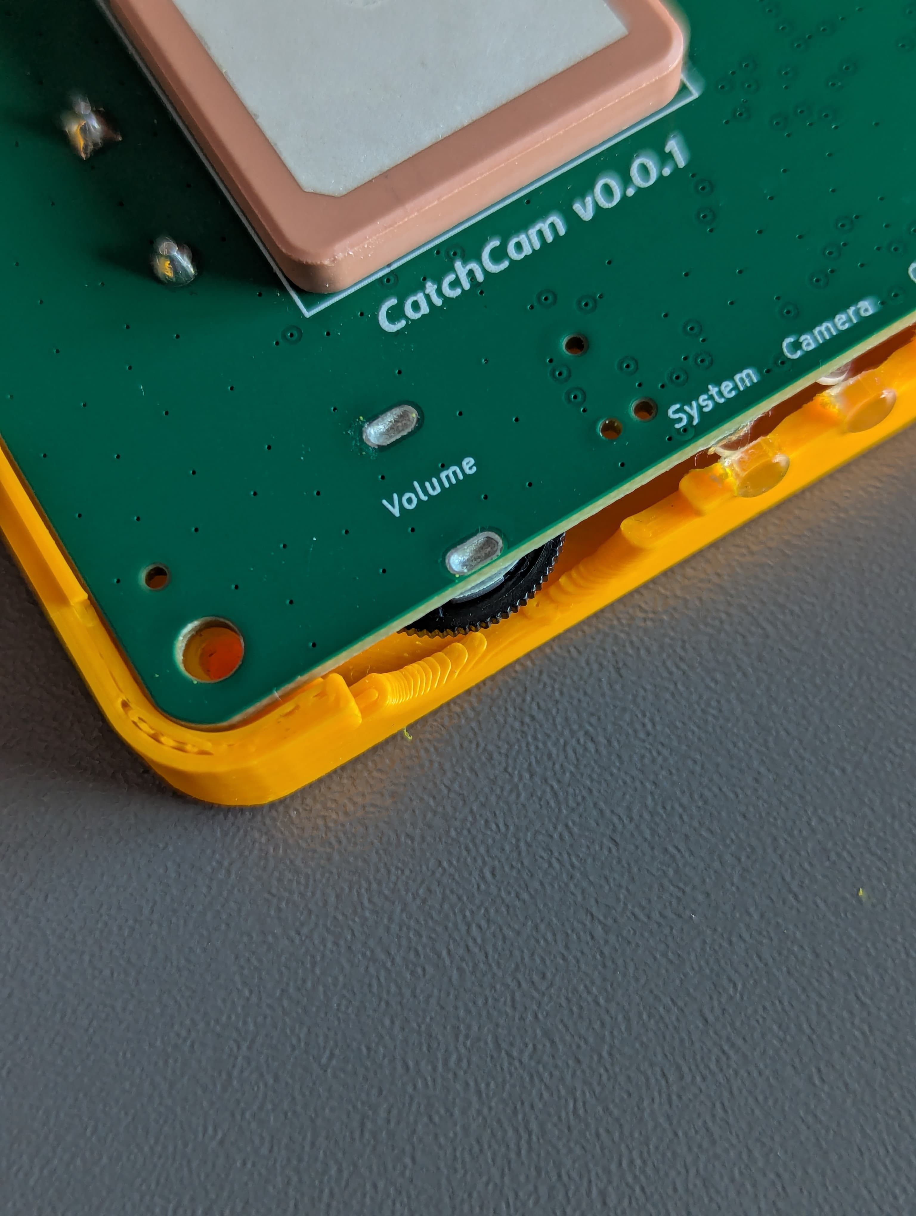
Catchcam enclosure dimensions are 65x65x18 mm. The enclosure is designed to be 3D printed in two parts: the top and the bottom part. The top and bottom dividing plane cuts trough the middle of th e USB-C, LEDs and the Volume rotary knob because those parts are sticking out of the PCB and I wanted to make assembly as easy as possible. The bottom part of the enclosure has a circular cutout for the speaker while the top part is solid. The two parts are held together with four ISO7046 M3x14 screws located in the corners of the enclosure. The enclosure will be printed in PLA, but I might try printing it in ABS or PETG for better durability.
Design Iterations
The first prototype of the enclosure had screws located at the top of the enclosure, but I’ve decided to move them to the bottom because I wanted to make the top part as clean as possible. The screw holes are designed to be self-tapping so the screws can be screwed directly into the plastic without the need for a nut. I’ve also added a small chamfer to the screw holes so the screws can be easily screwed in. For the next iteration of the enclosure, I would like to avoid using screws for assembly and try to design a snap-fit mechanism.
LED Diffuser Pipes
I’ve also added circular cutouts for the LEDs in order to include small plastic light diffuser pipes in order to make the LEDs more visible. The diffuser pipes are glued to the enclosure with a small amount of super glue.
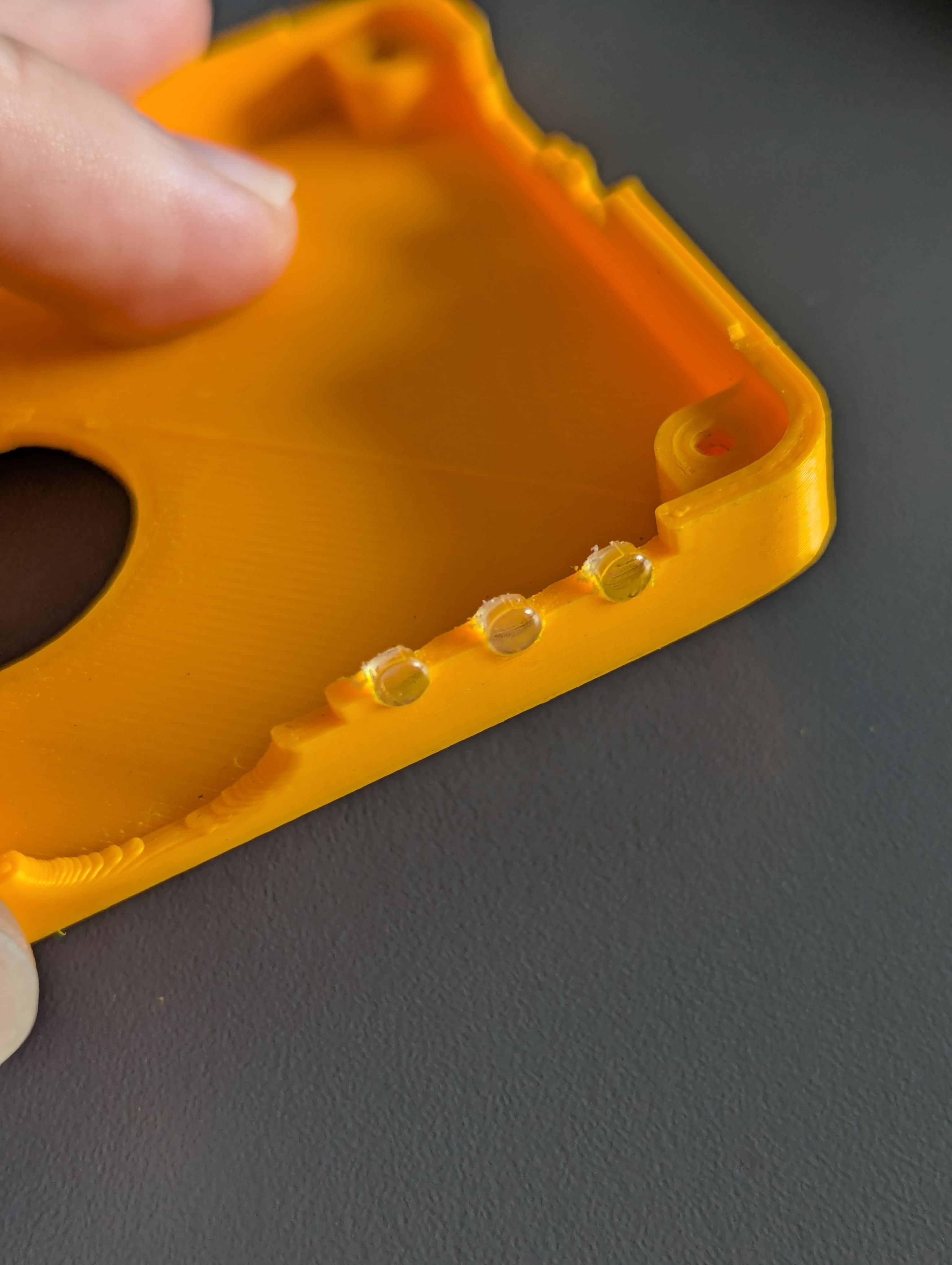
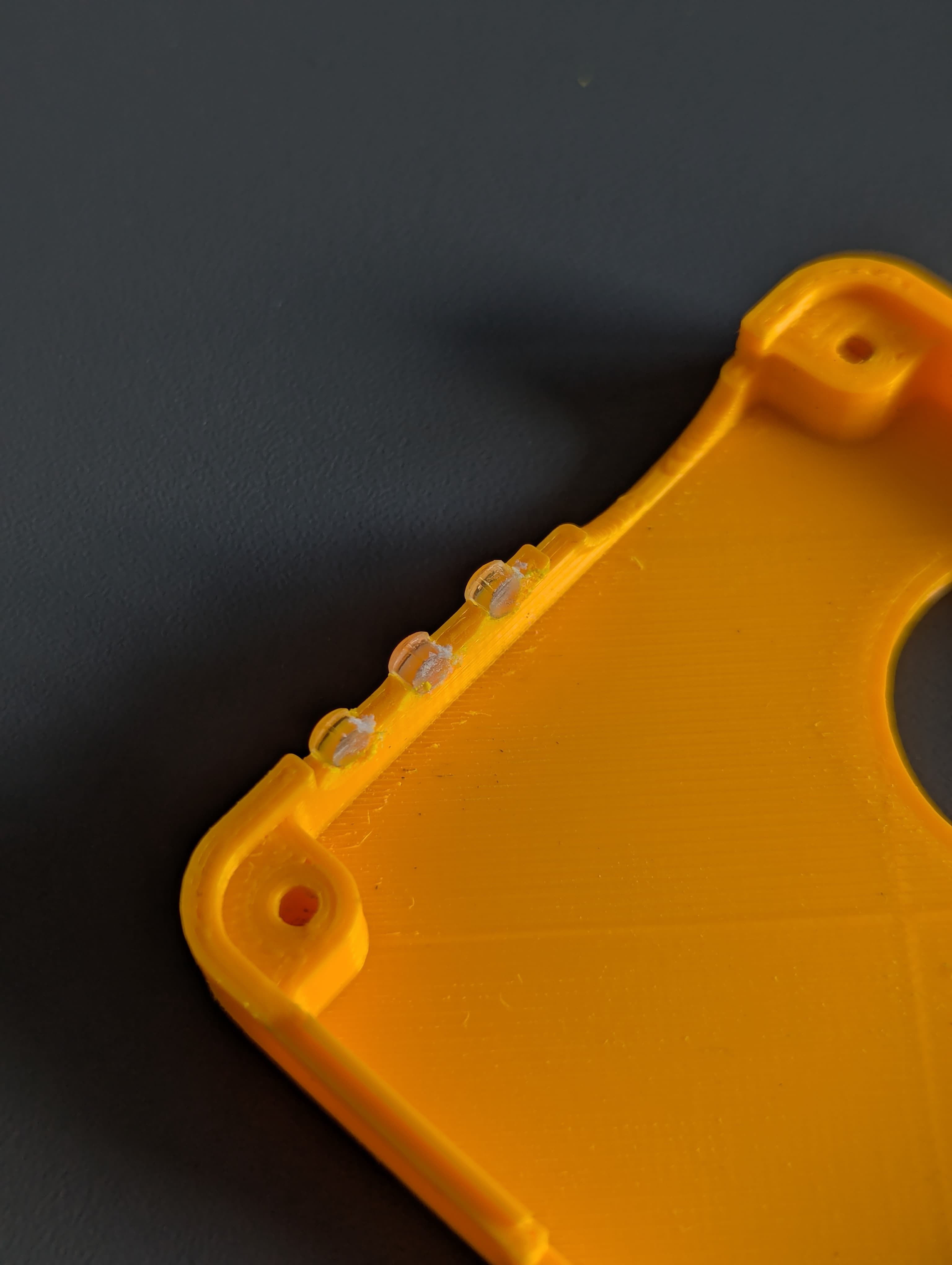
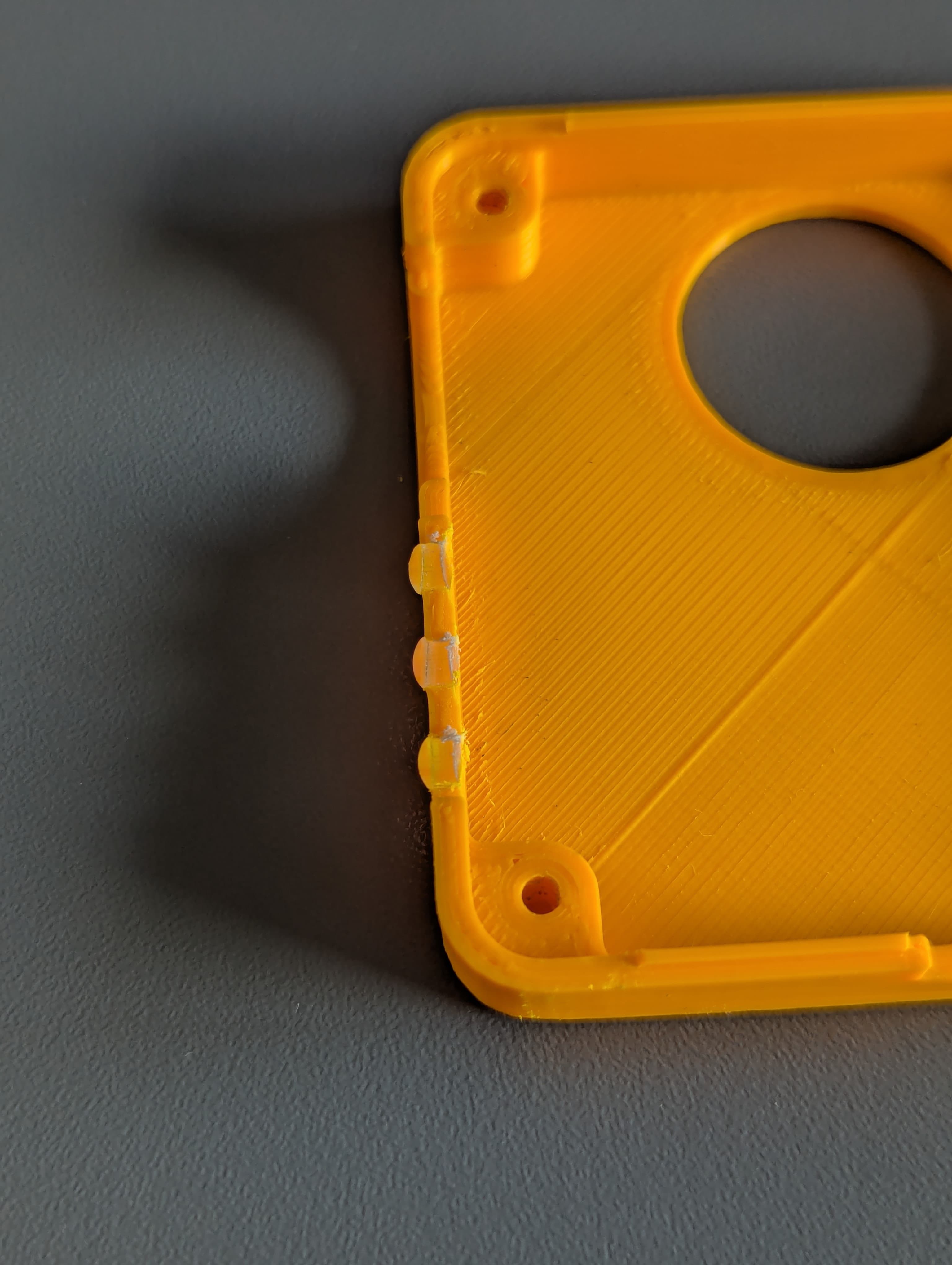
As you saw in the image above, the diffuser pipes holes are splitted in half for easier assembly, however, I would like to experiment with a solid hole in the future so the diffuser pipes can be pressed in without the need for glue. Moreover, I have a problem with the diffuser pipes because they are not the right length and they are interfering with the LEDs so I need to grind them down a bit in order to make them fit nicely.
Antenna Considerations
I’ve especially paid attention to the distance between the PCB and the top part of the enclosure because of findings in the Molex GPS Ceramic Antenna application specification document where the GNSS antenna performance can be affected by the distance between the antenna and the ground plane. Currently, the distance is around 6.37 mm and that seems to be working fine.
3D Print and Assembly
The top and bottom parts of the enclosure are meant to be printed on the largest surface placed on the print bed in order to avoid printing unnecessary support material. As for the 3D design guidance, I’ve used the UltiMaker Cura slicer software so I could see how the model would be sliced and printed.
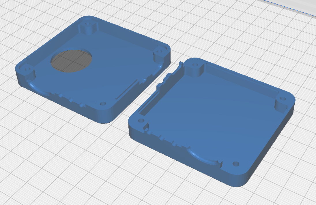
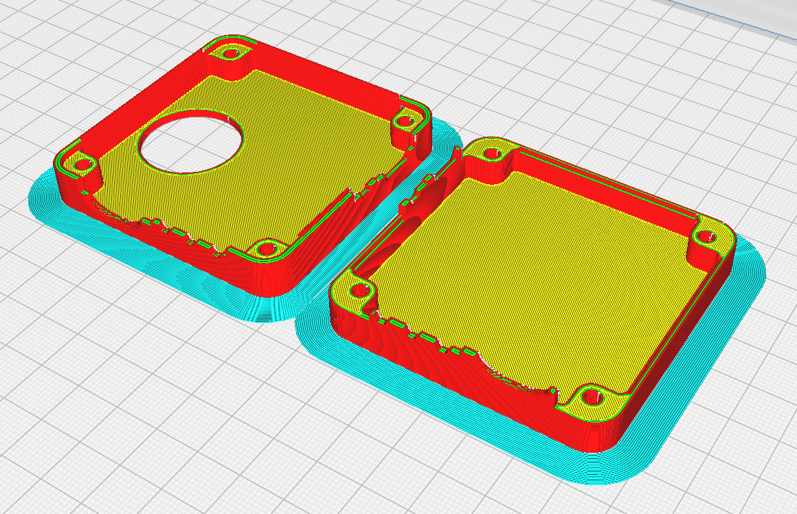
3D print came out quite nicely, although I had some problems with the first print because the printer was not calibrated properly (you can see missing walls around cutouts). Also, the fit was rather tight, so I had to grind down the edges a bit in order to make the assembly easier.
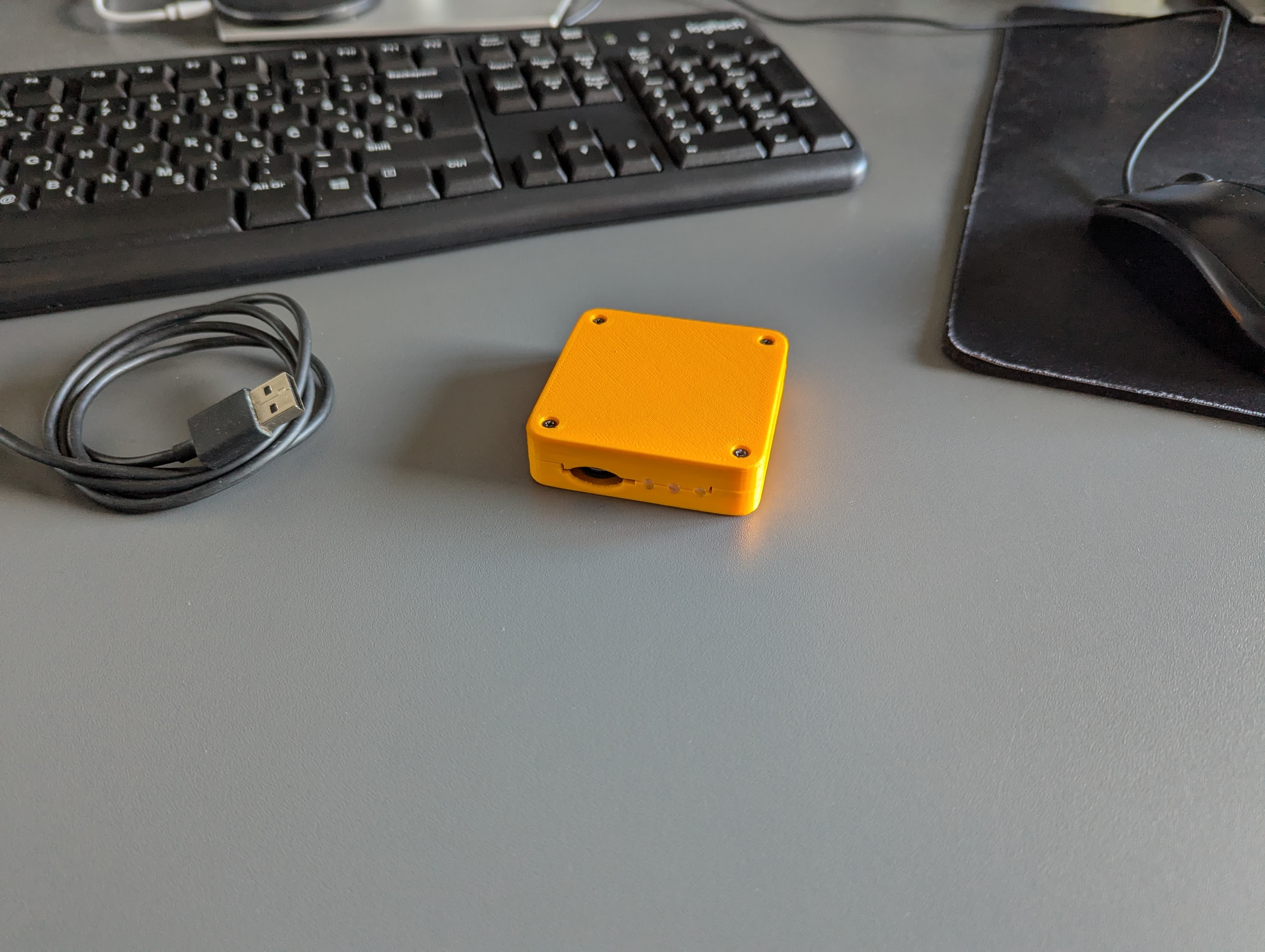
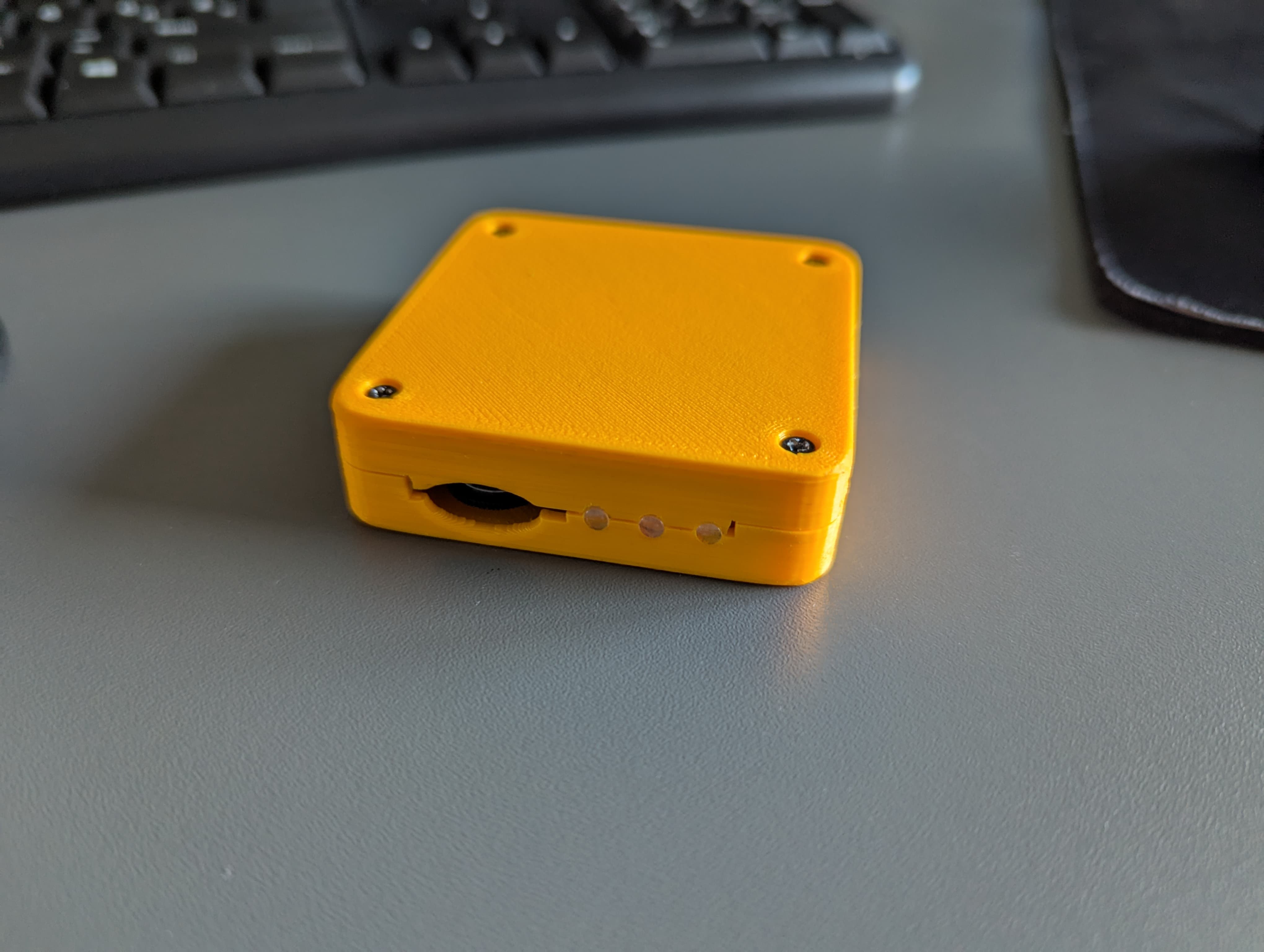
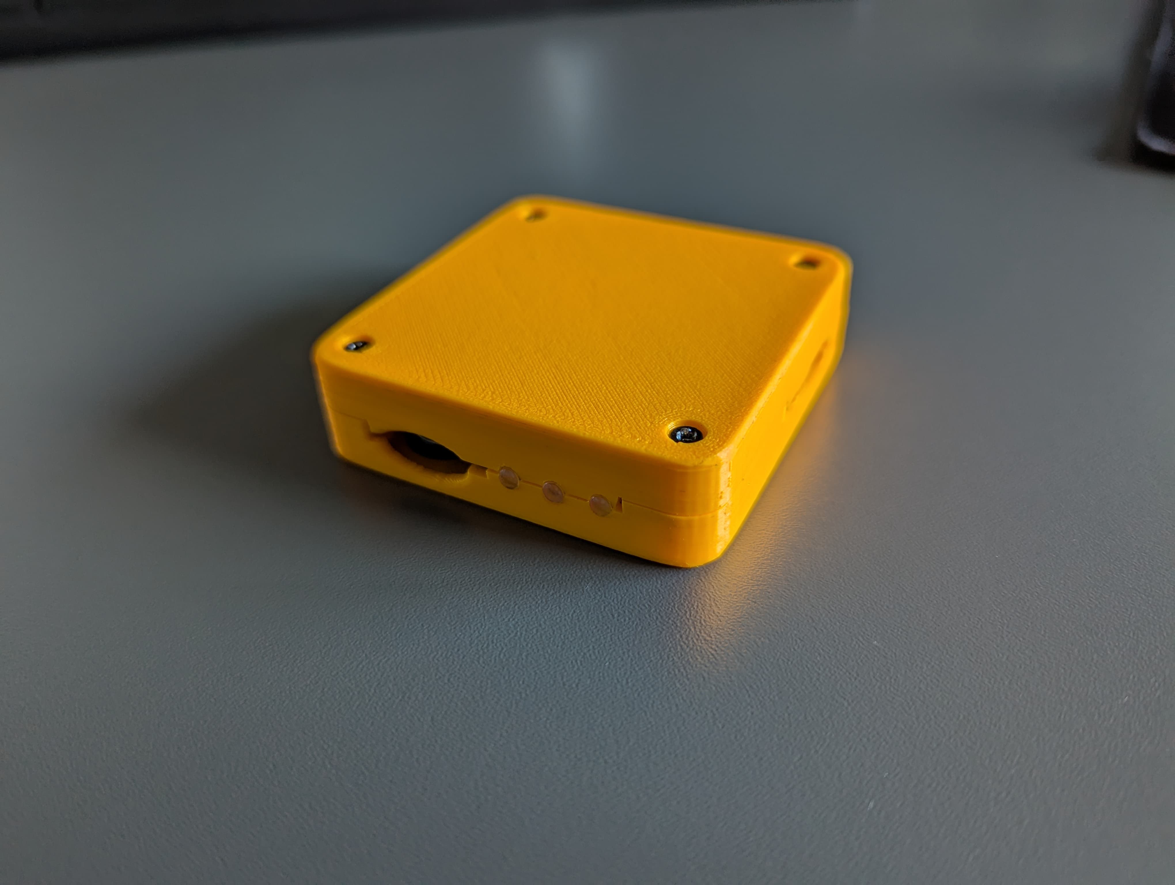
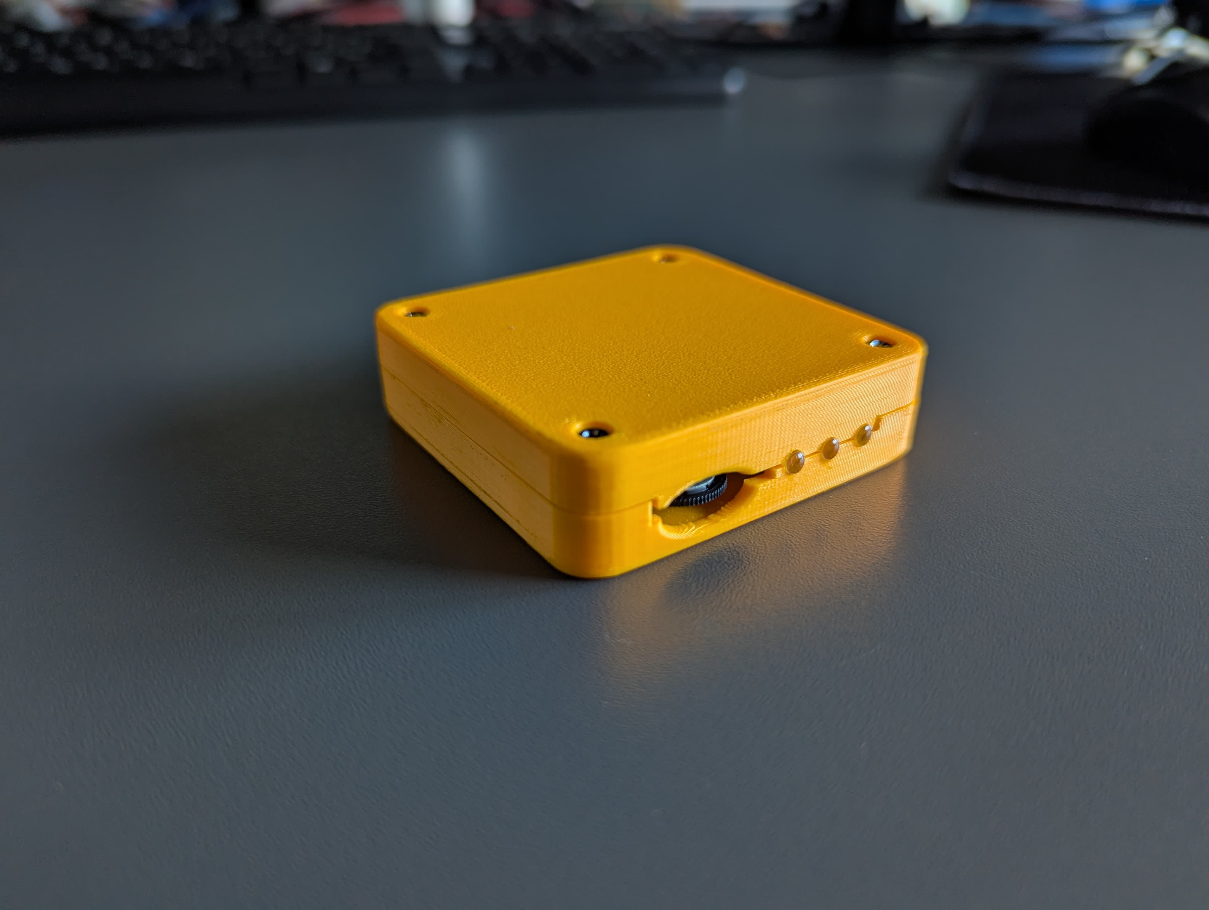
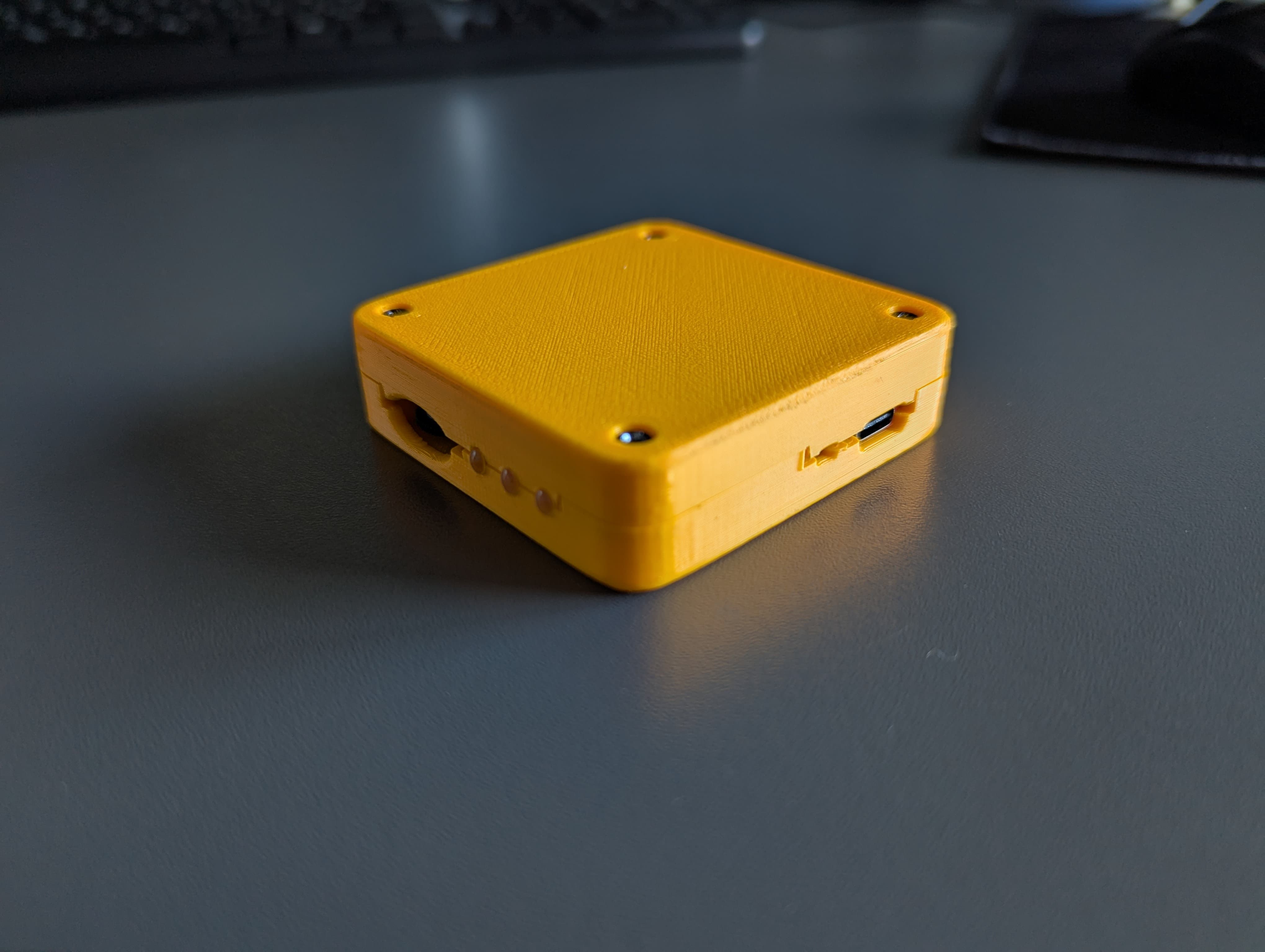
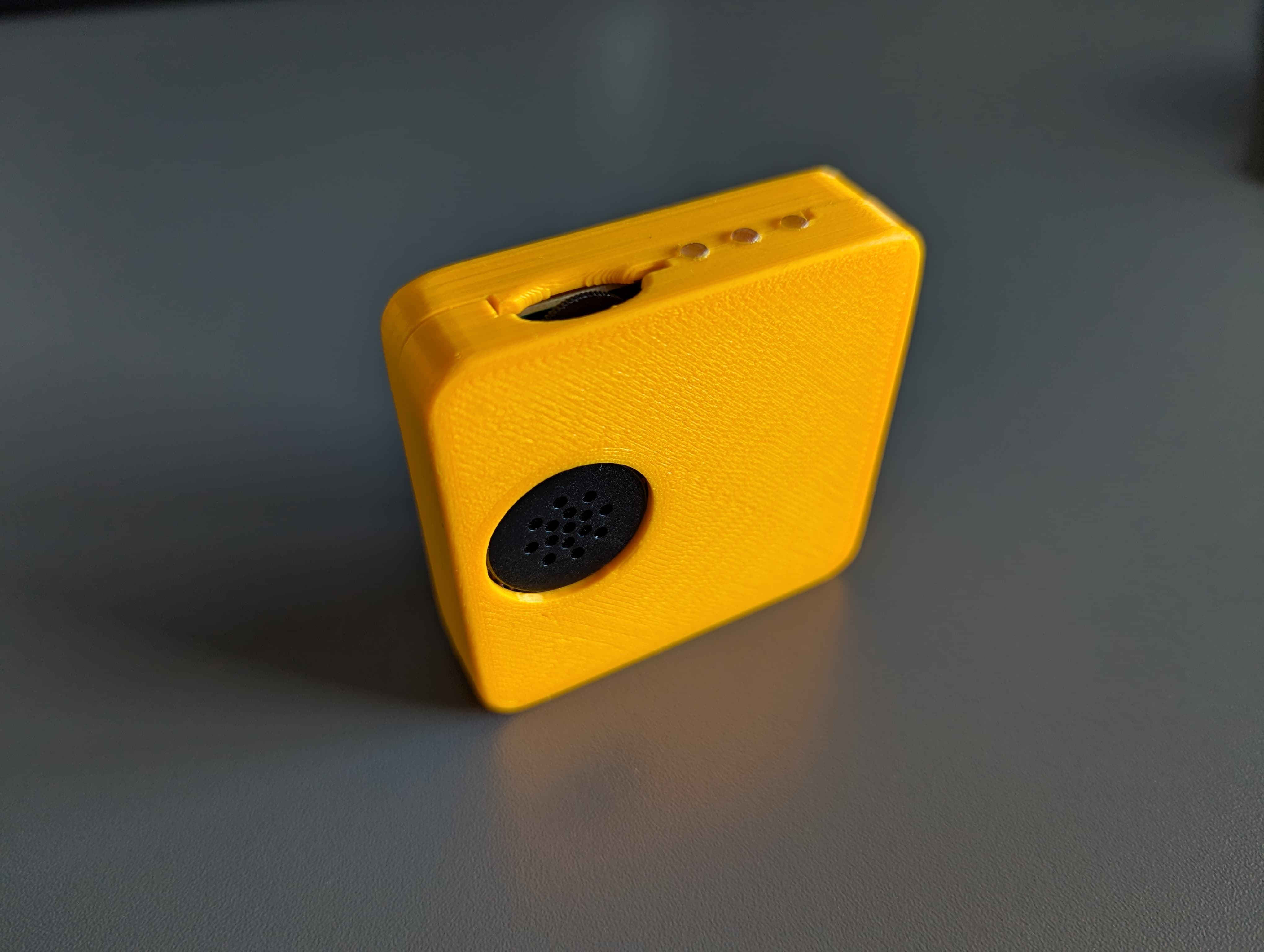
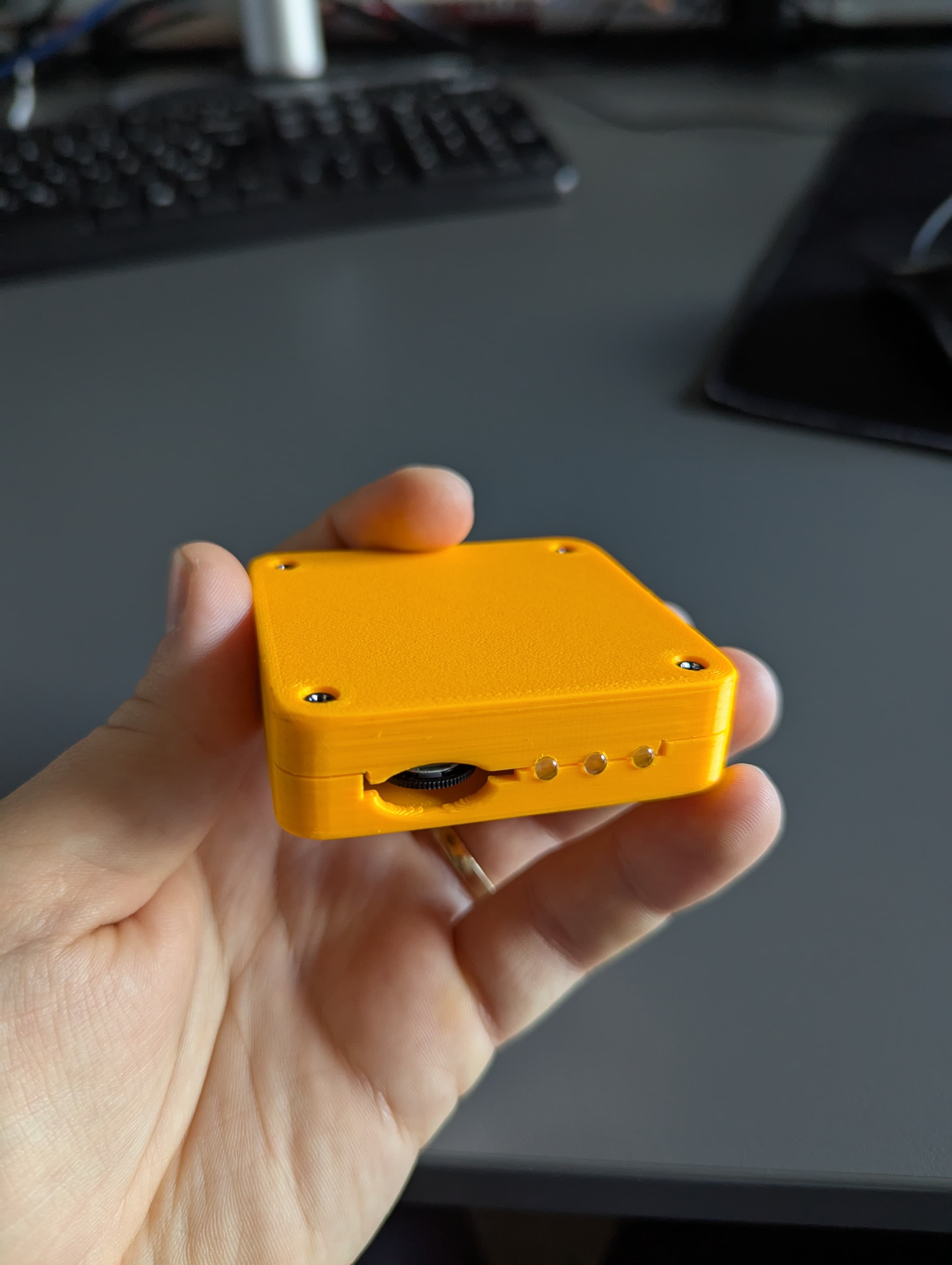
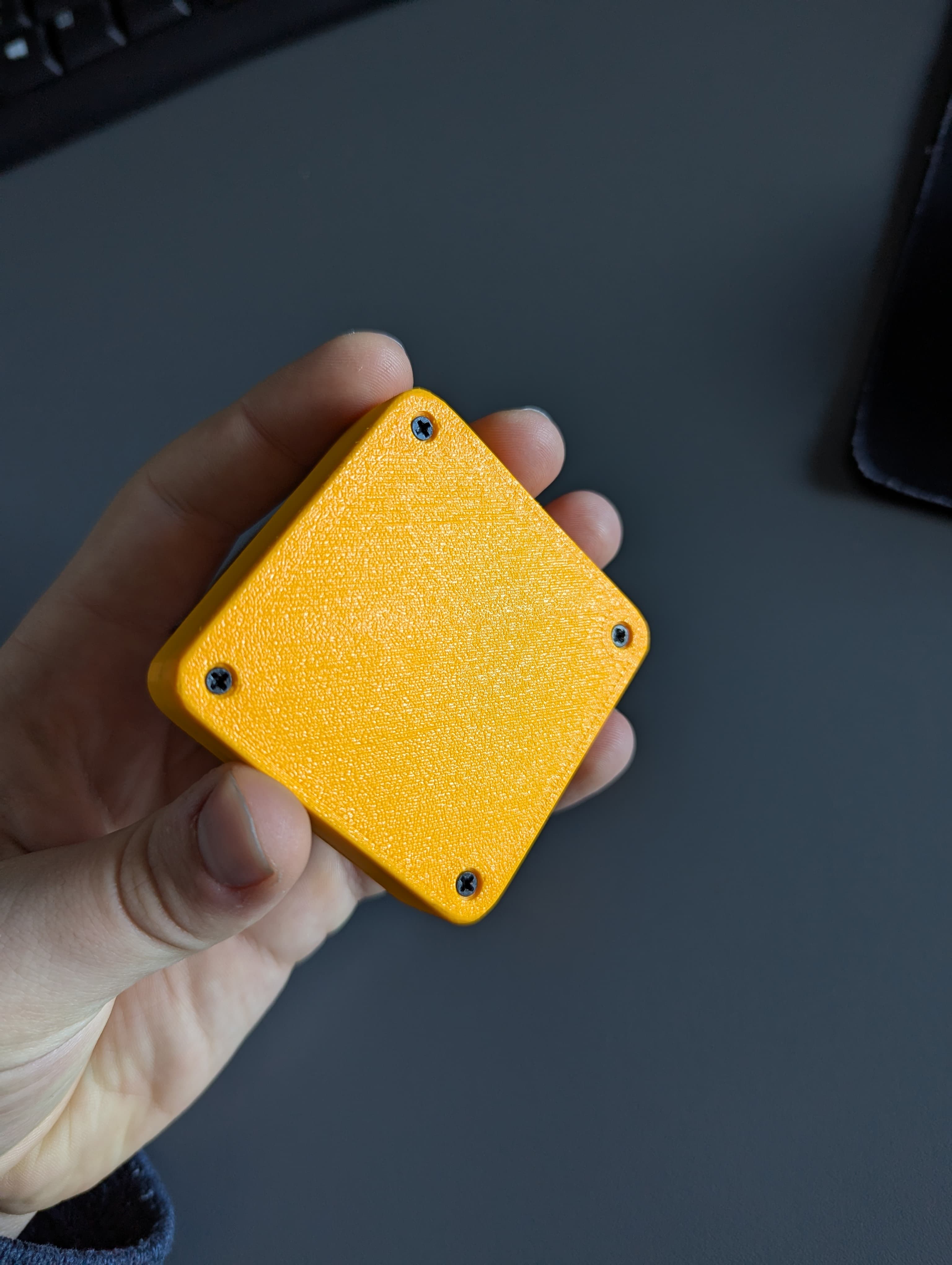
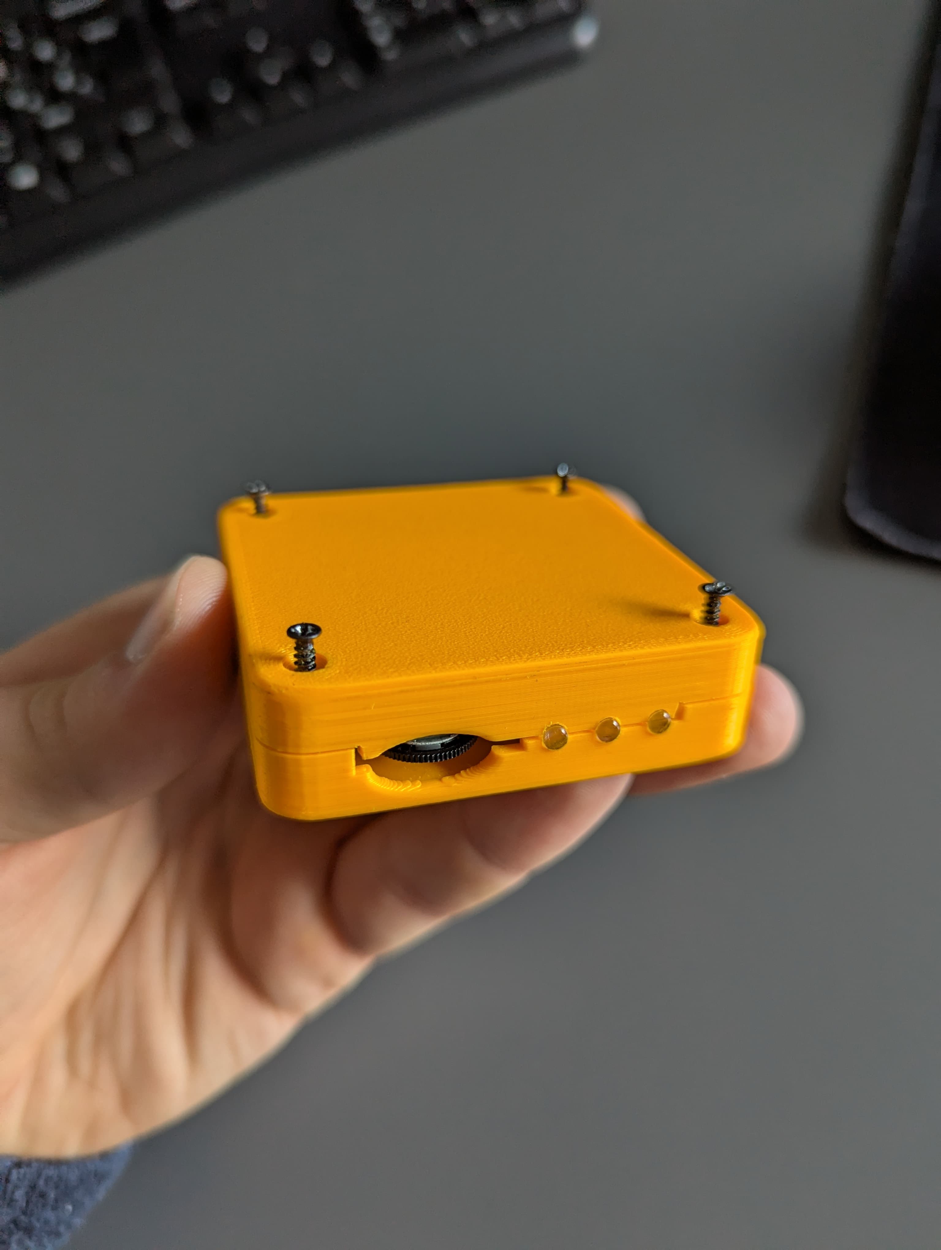


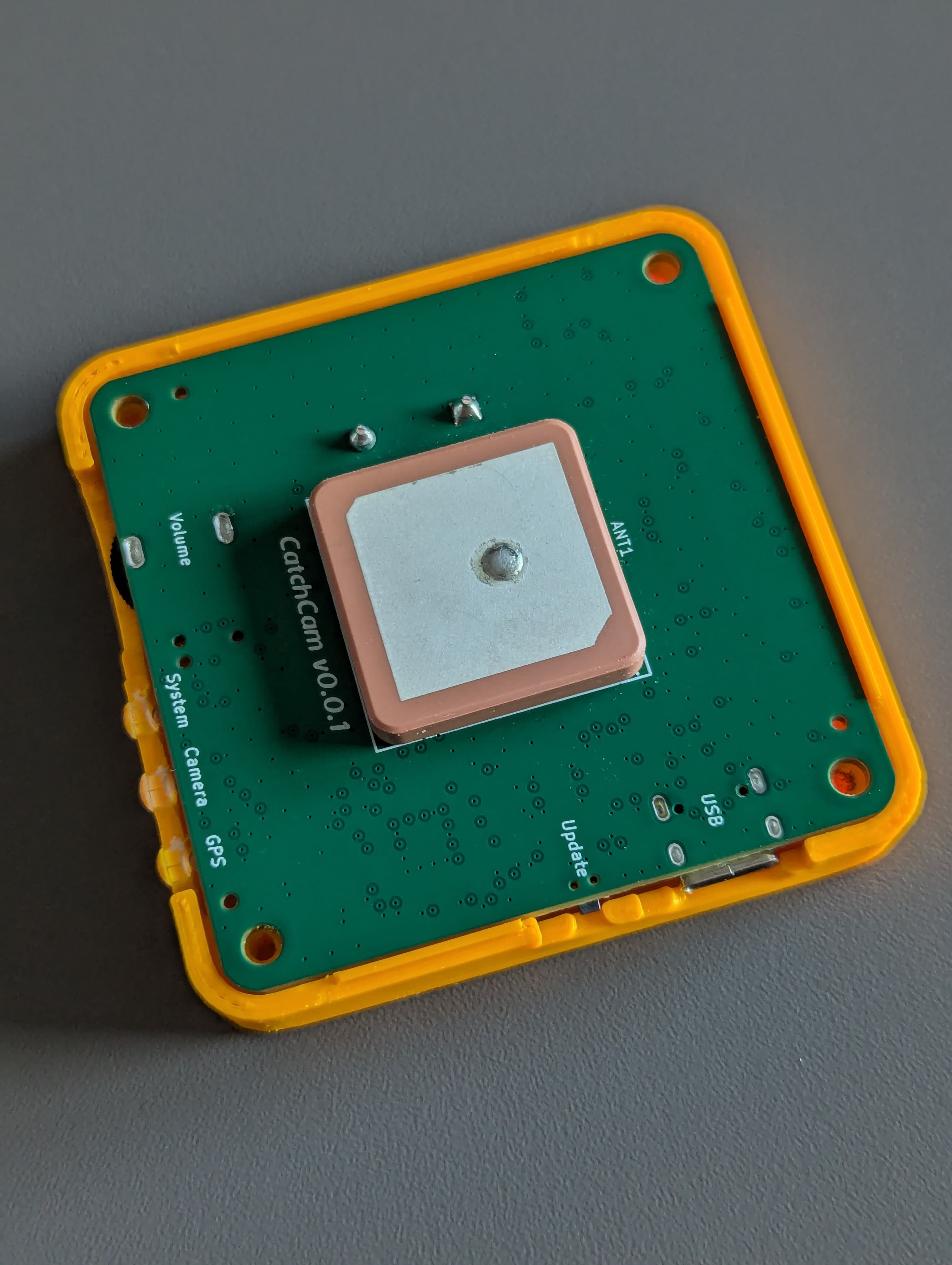
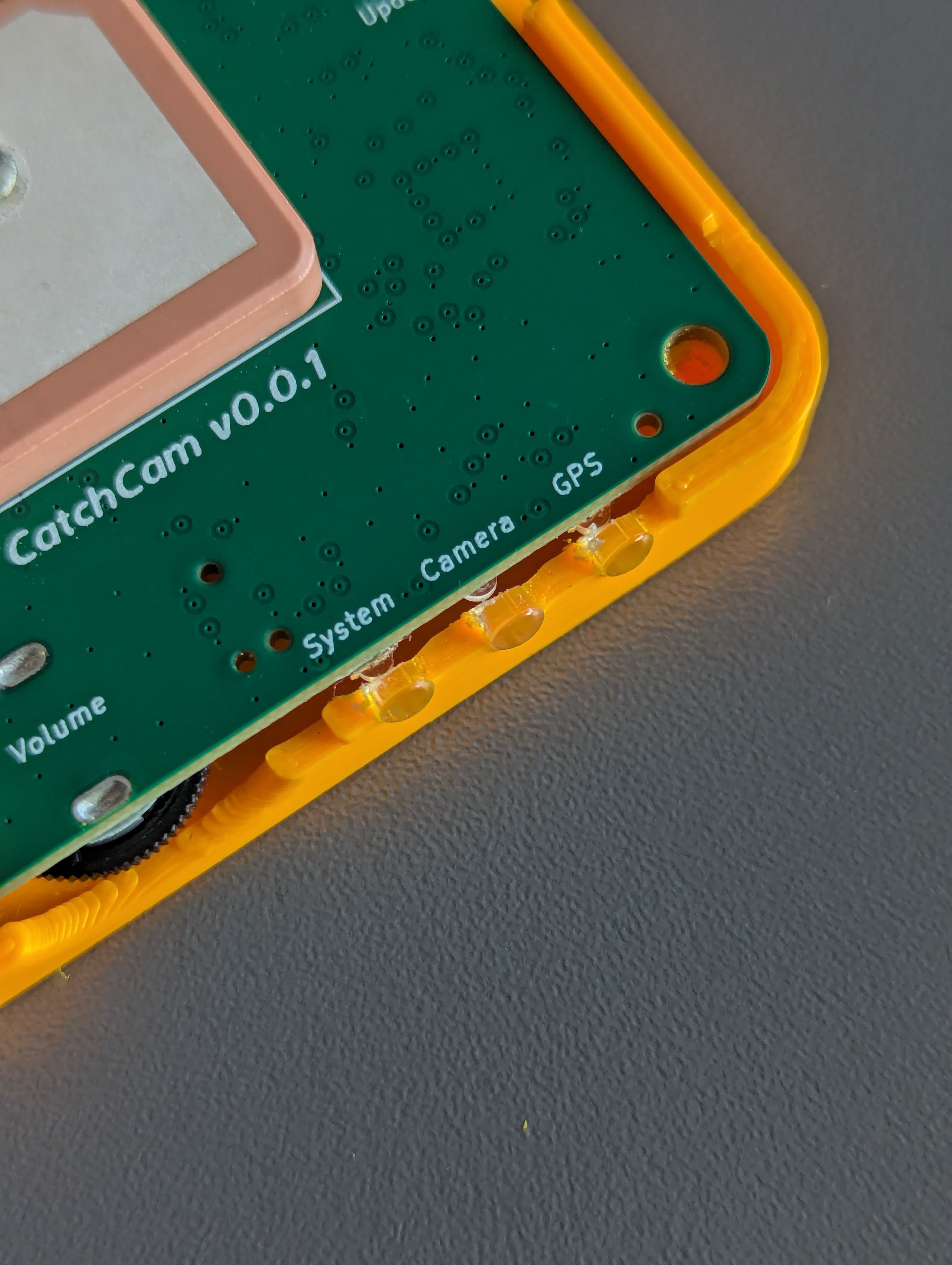
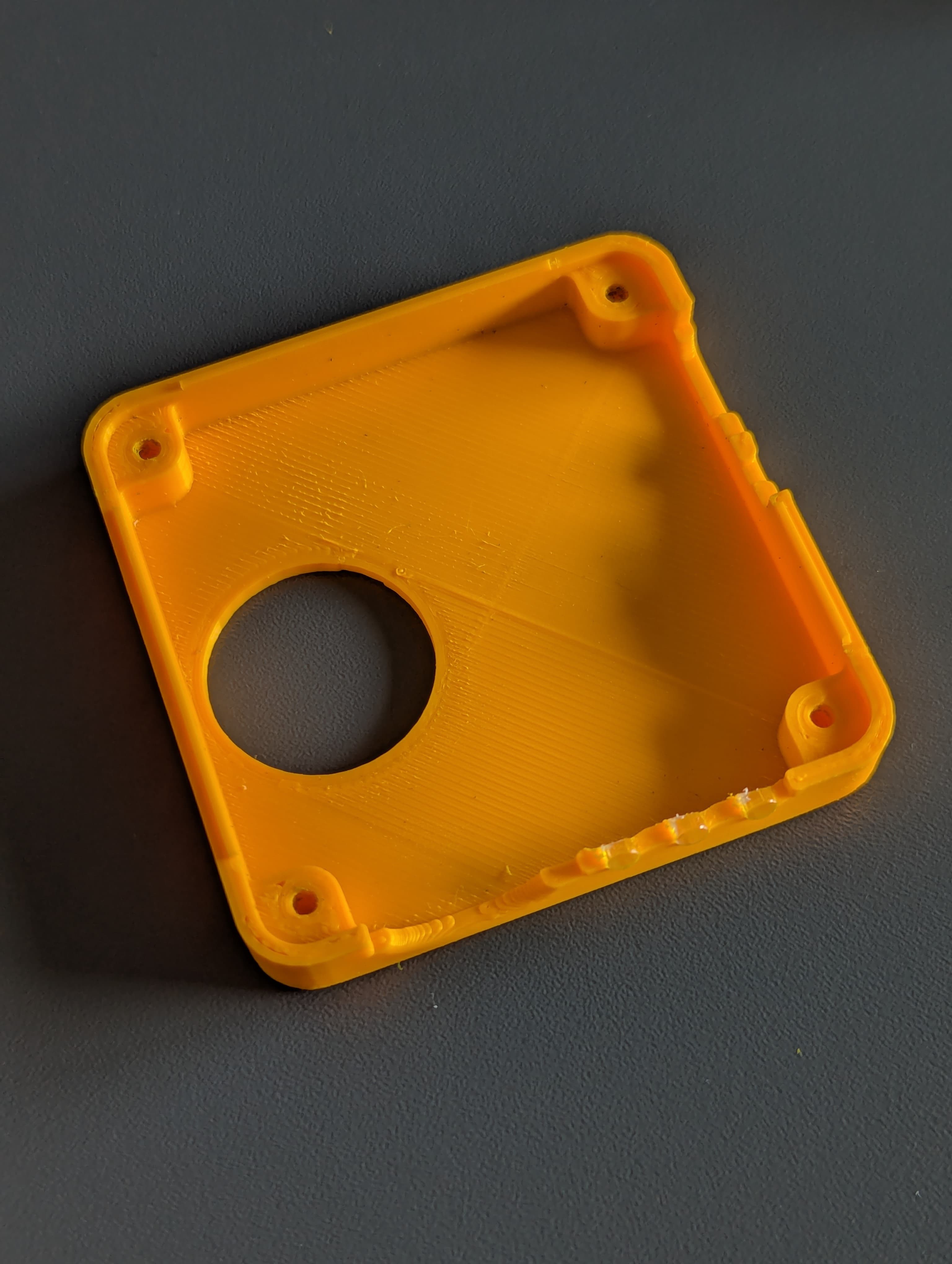
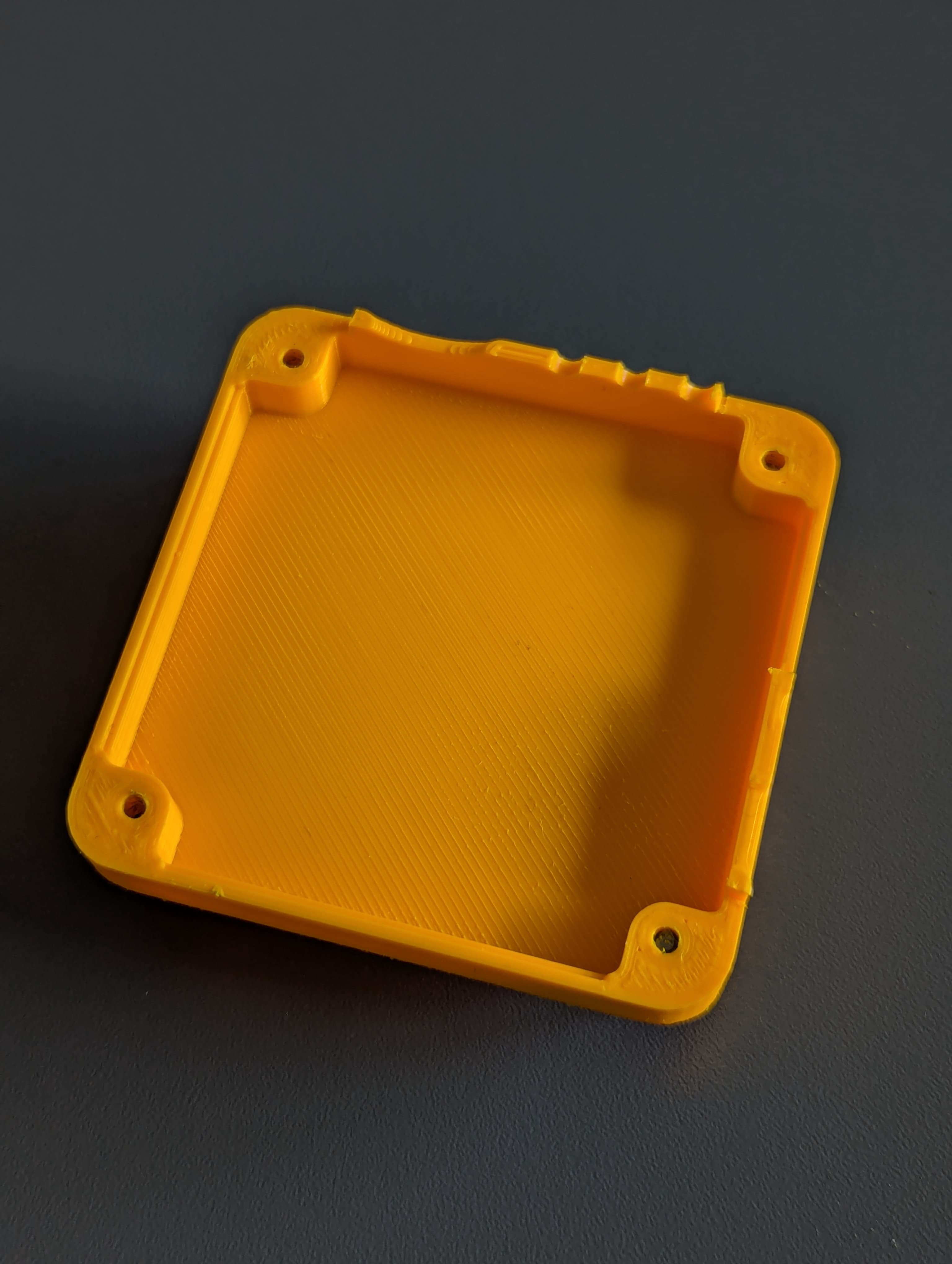
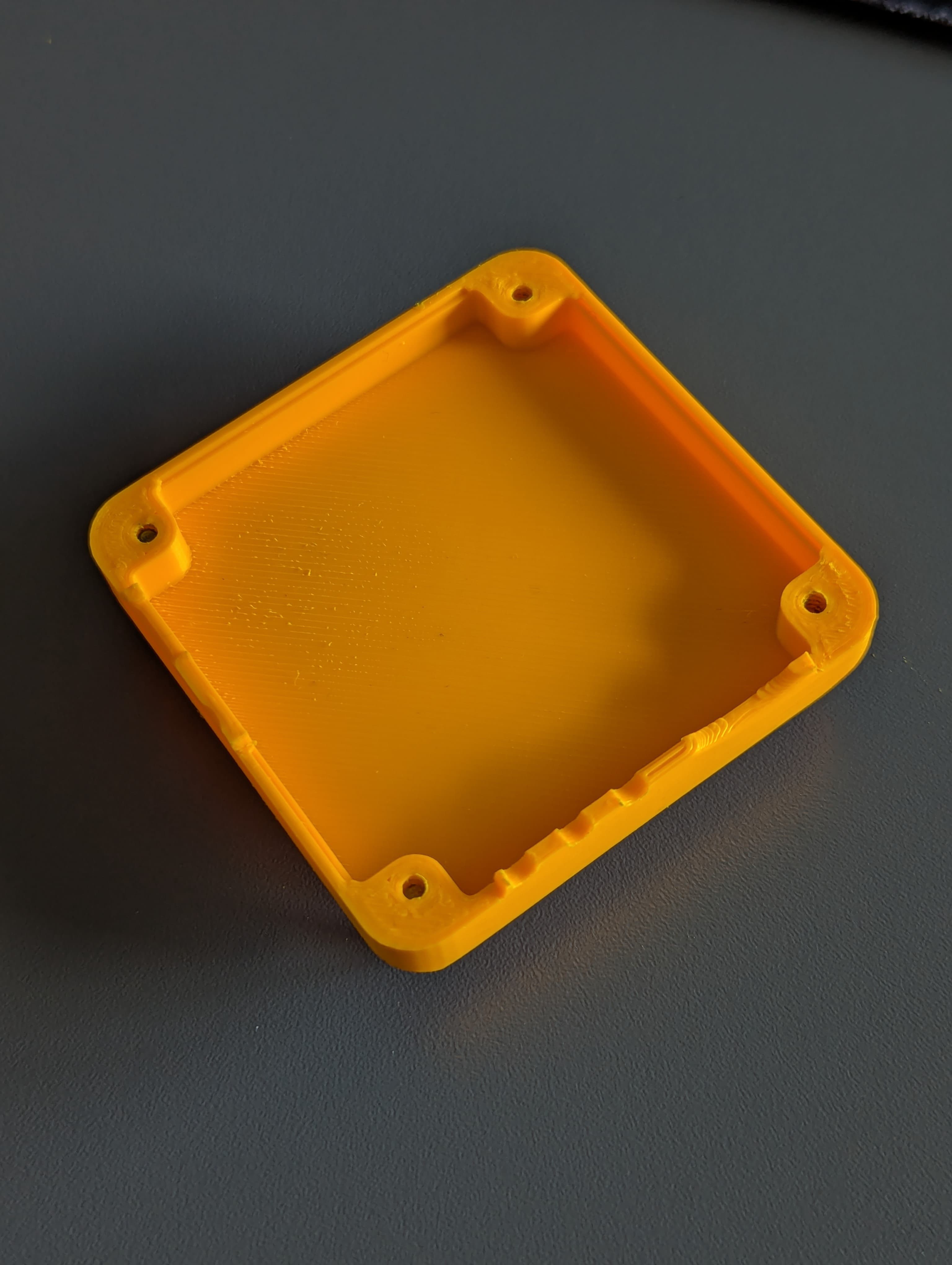
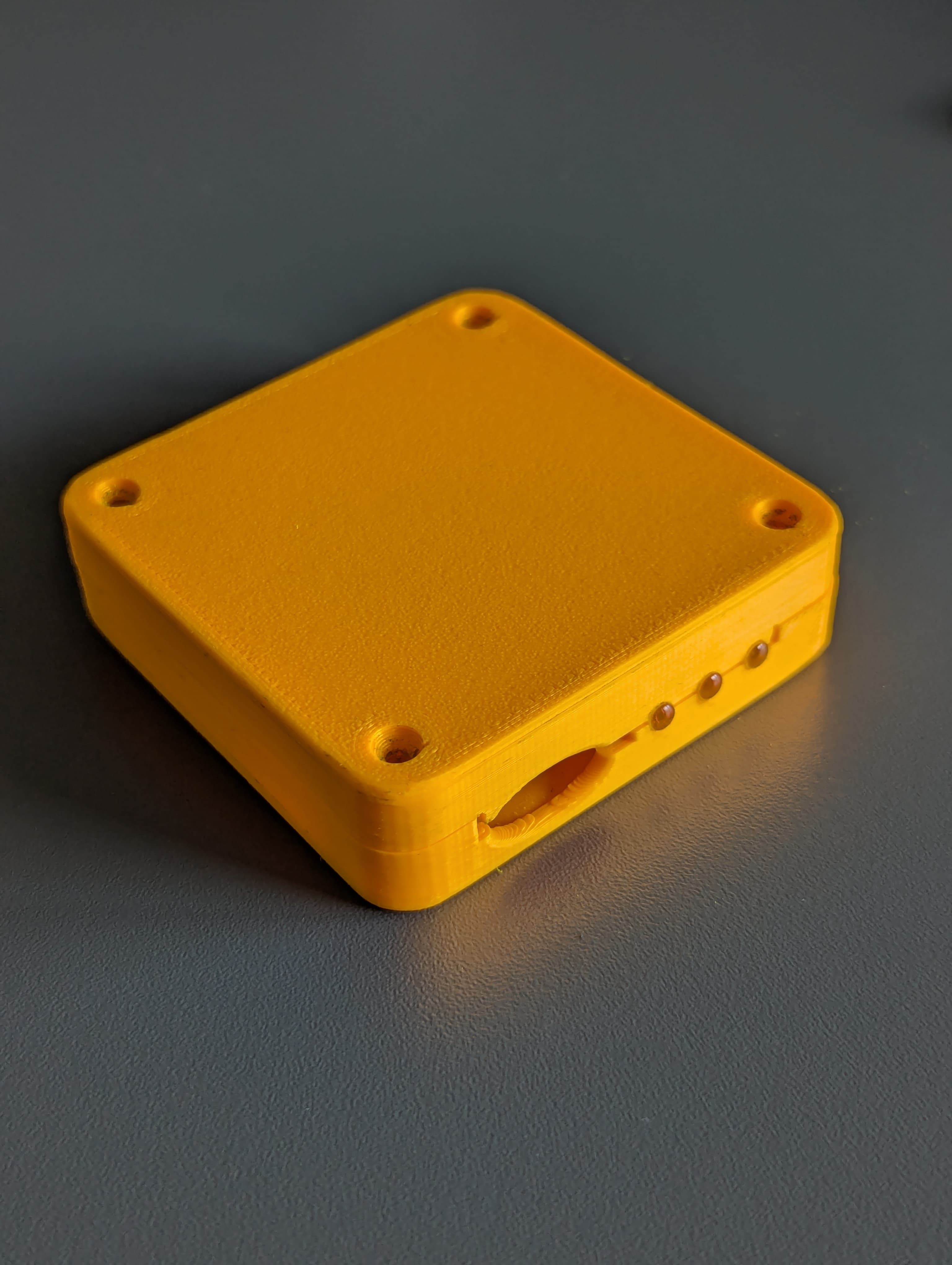
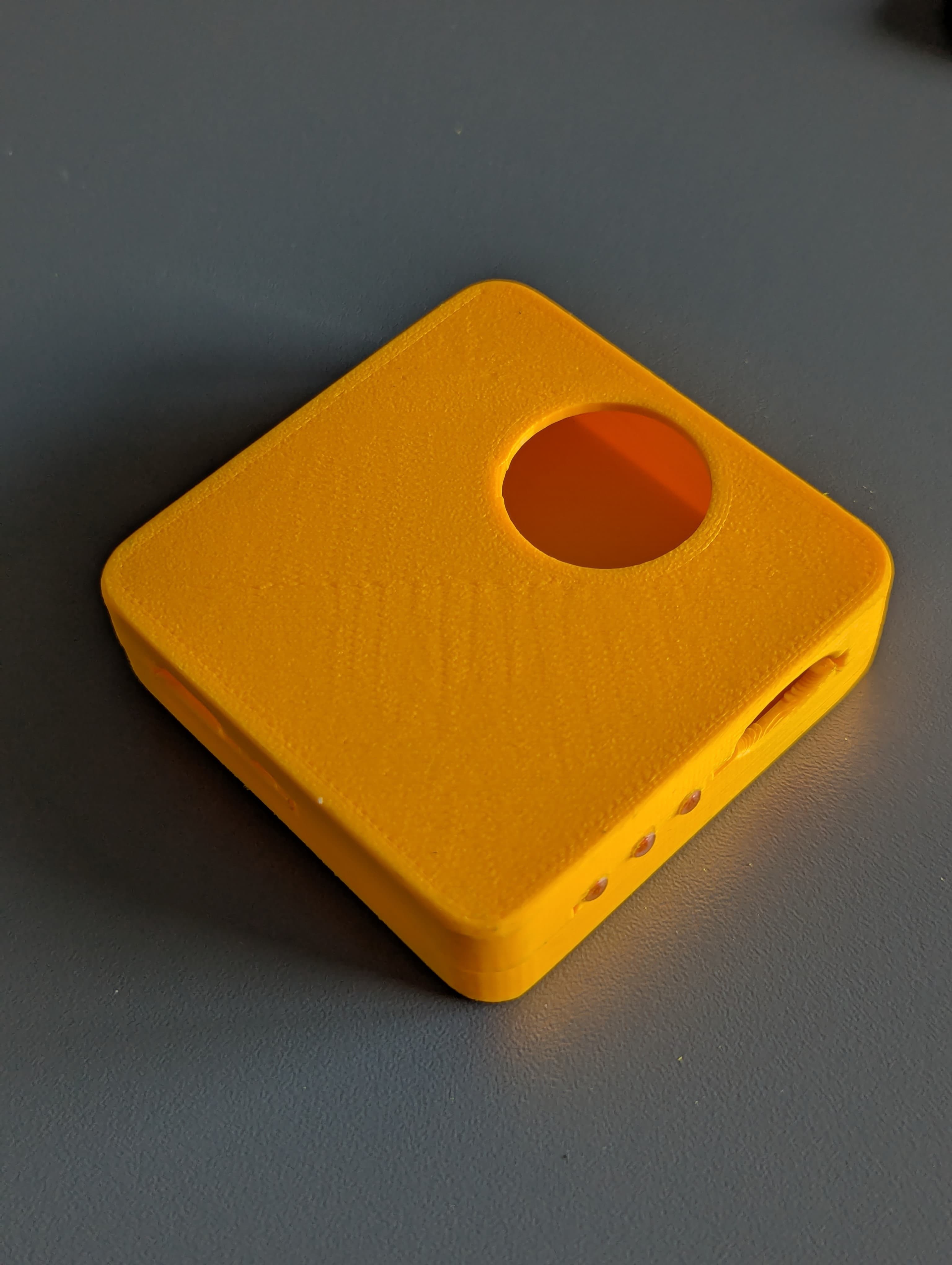
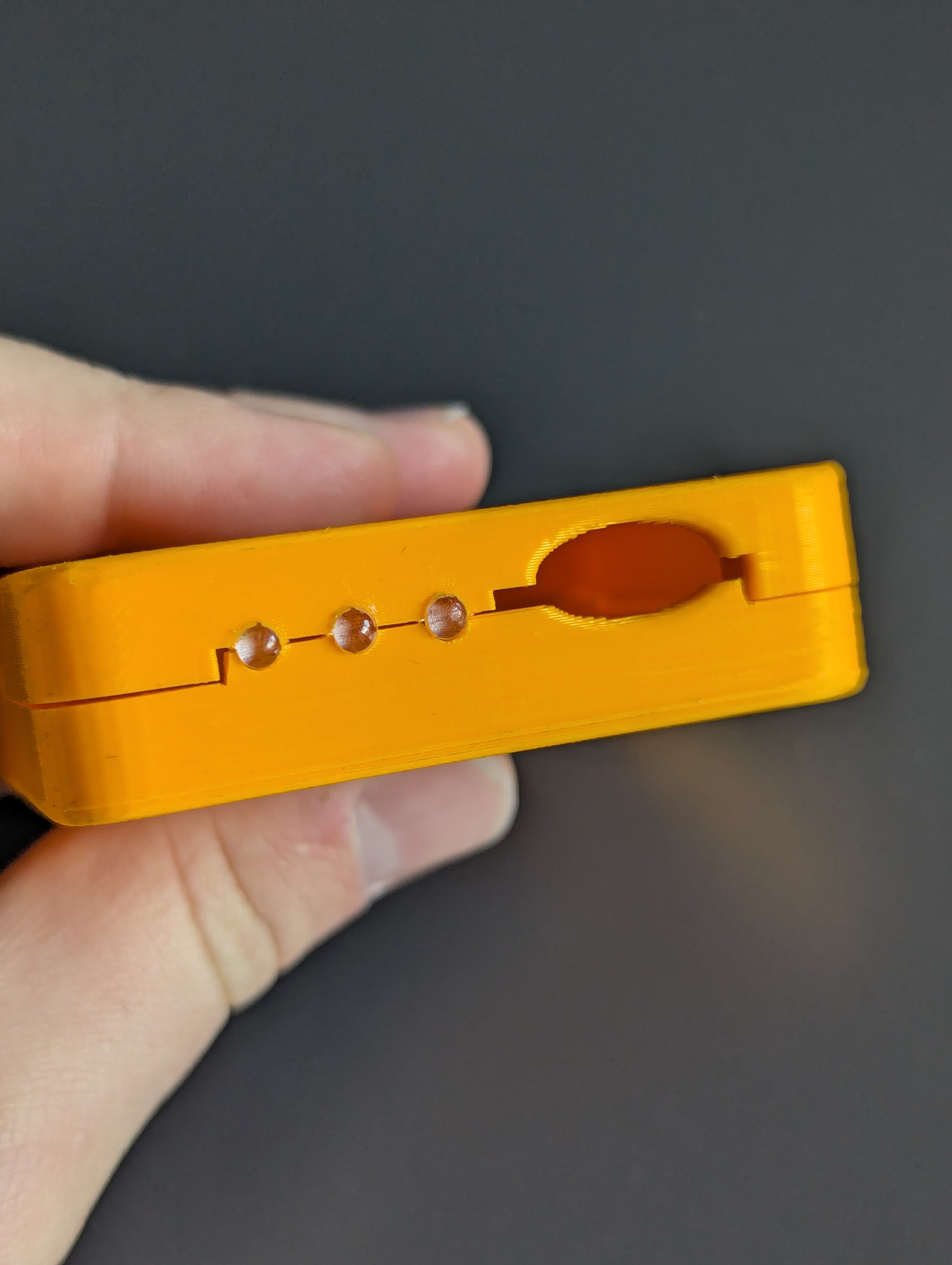
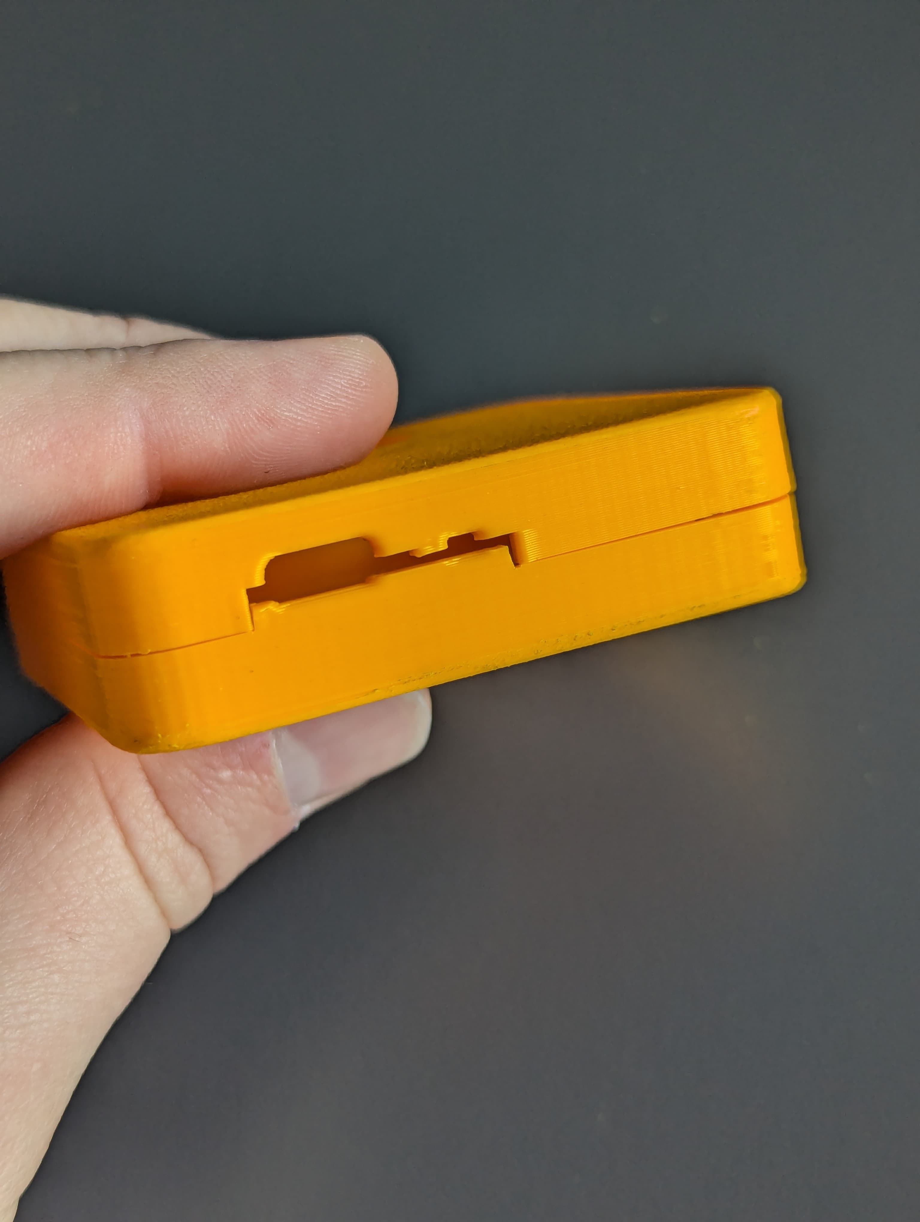
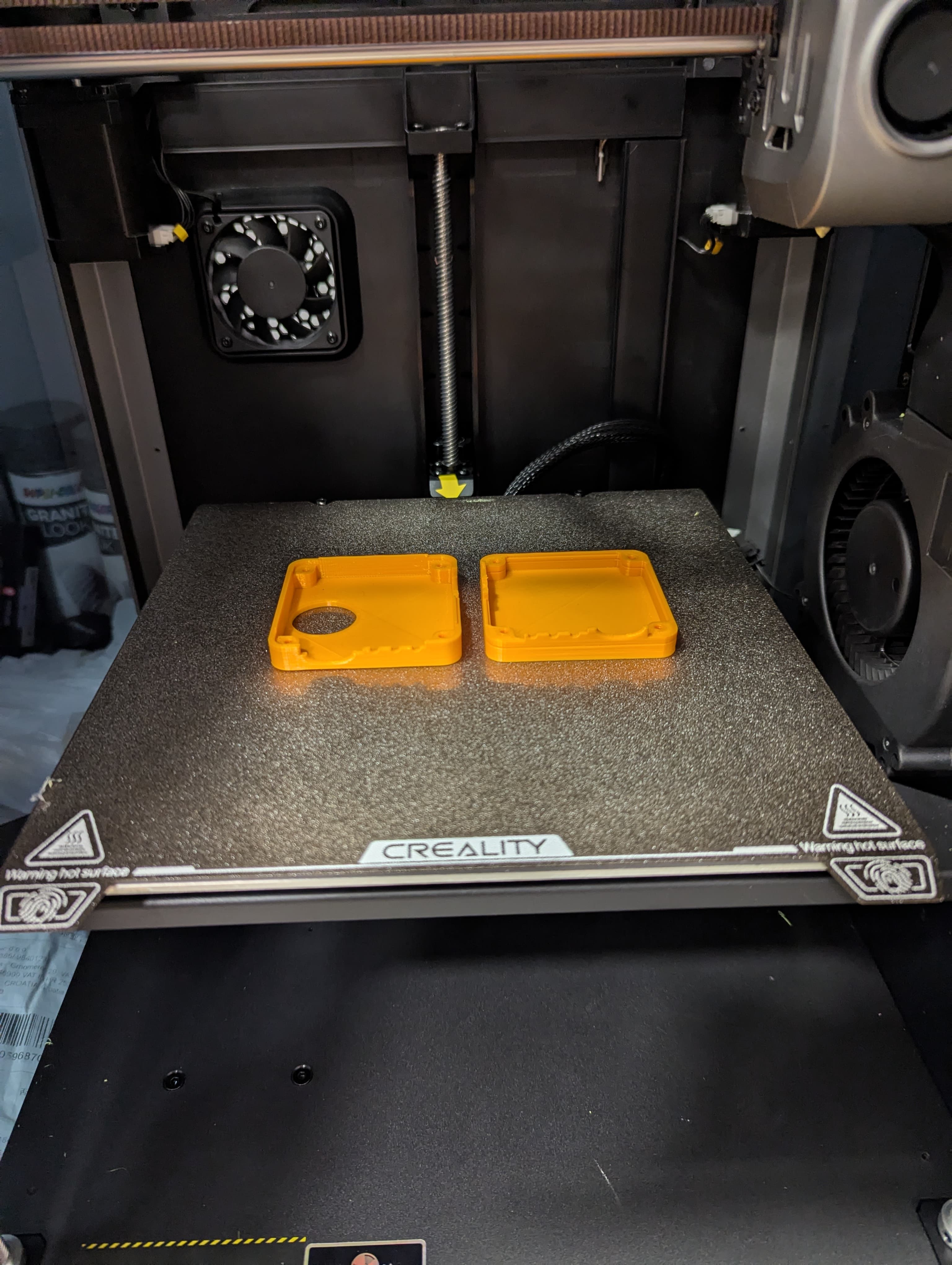
The second print came out much better and the fit was still tight, but I didn’t have to grind down the edges. Also, the walls around the cutouts were printed properly. Note that the screws are now on the bottom side of the enclosure.
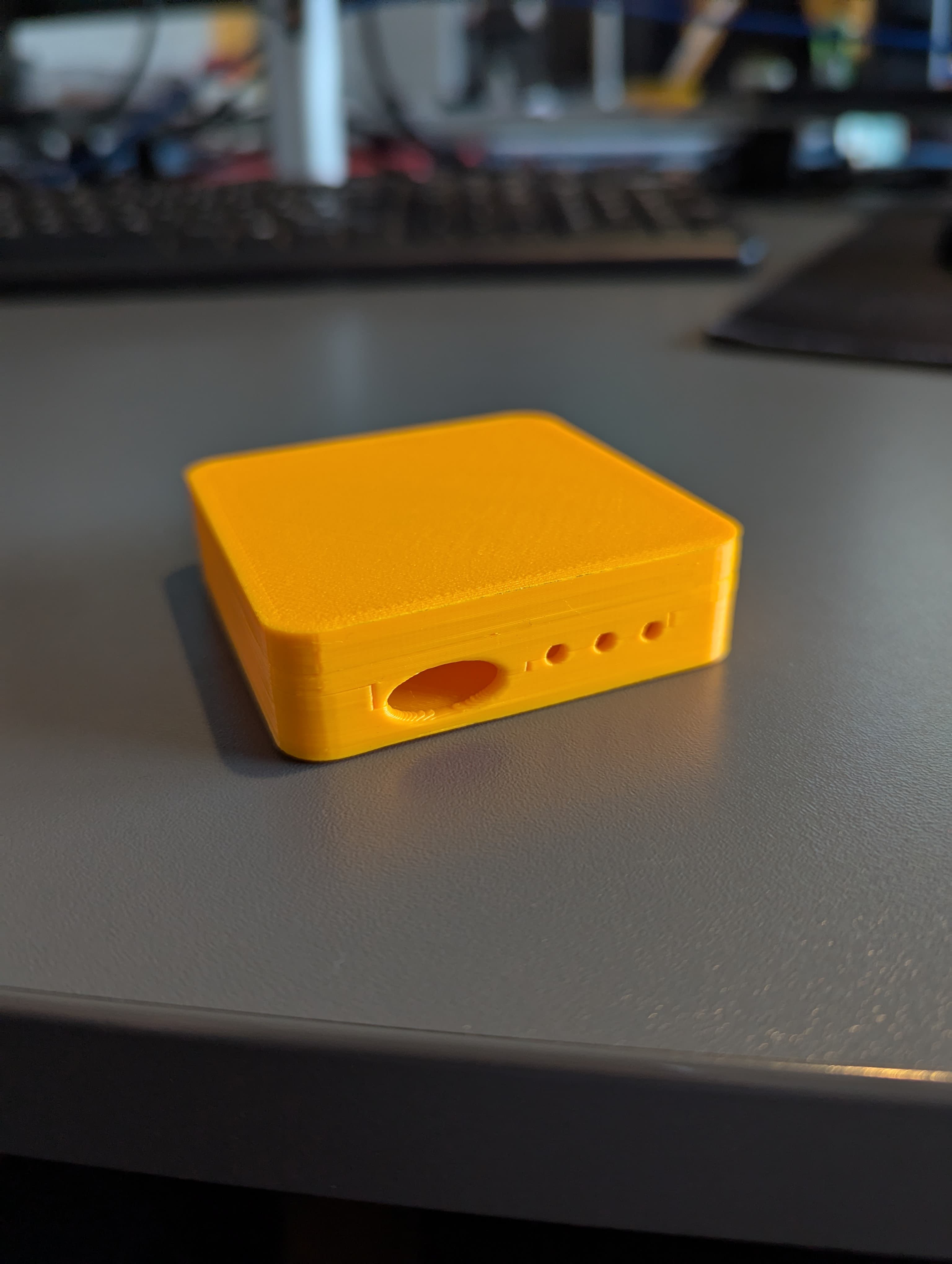
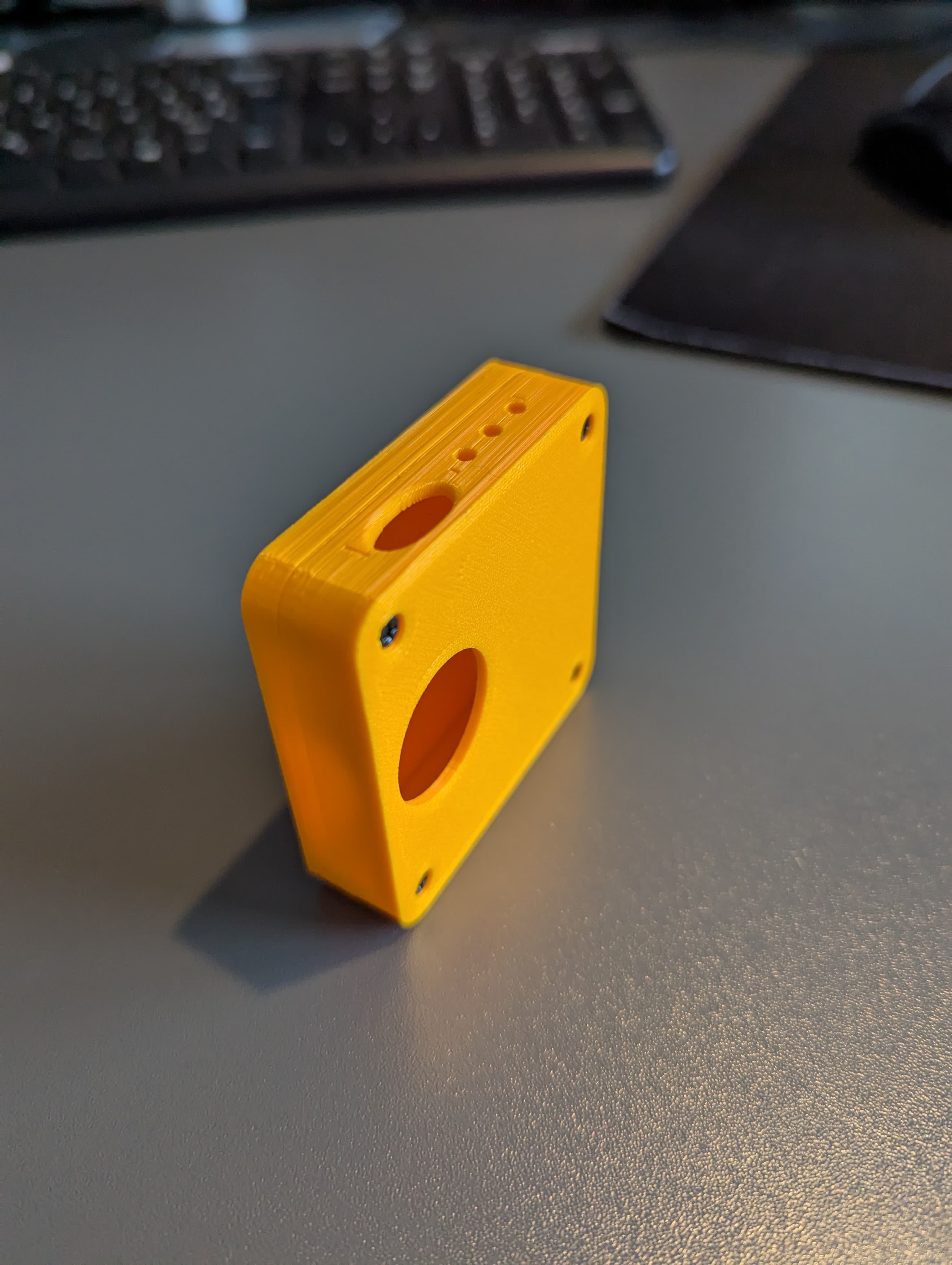
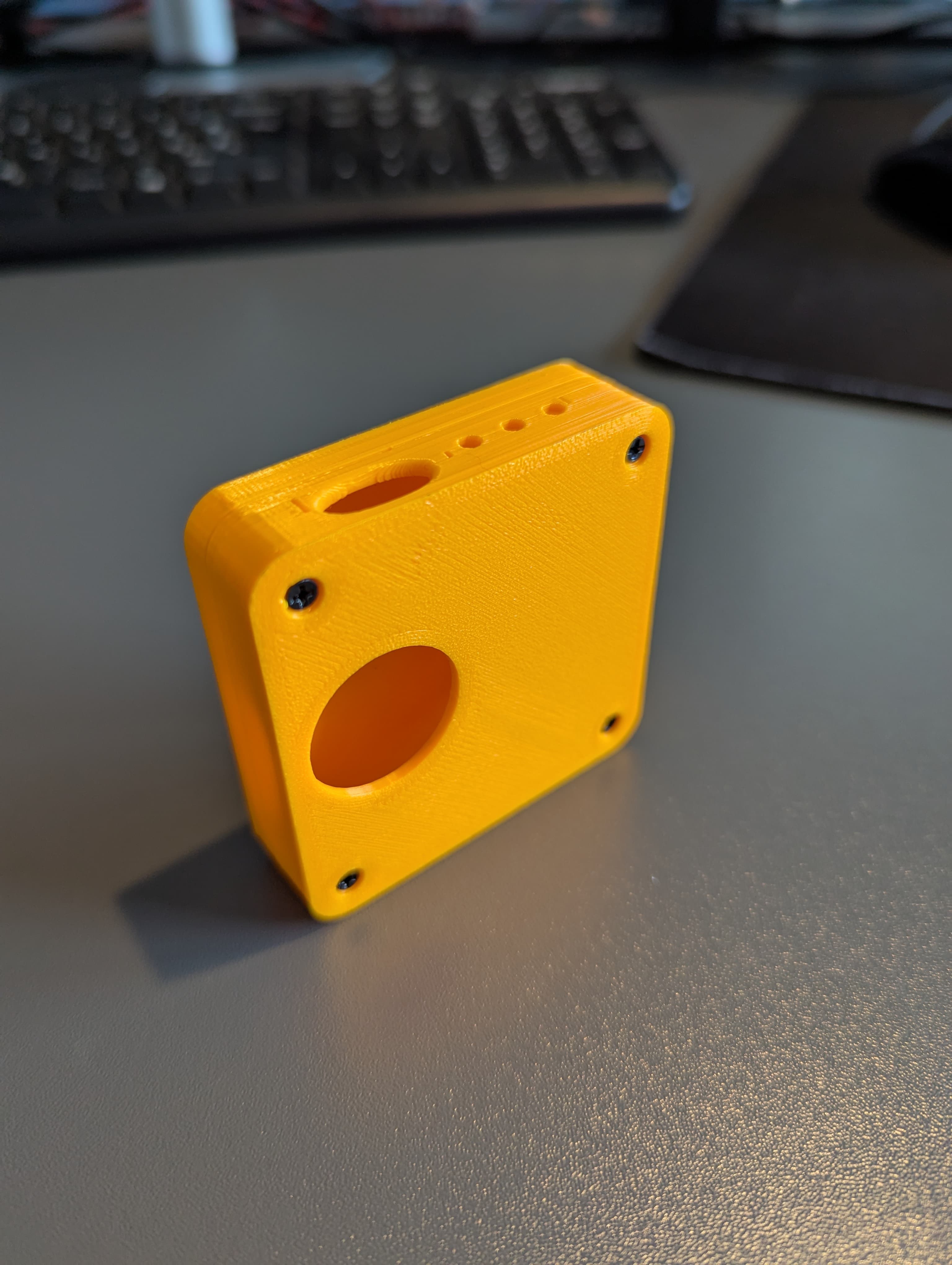
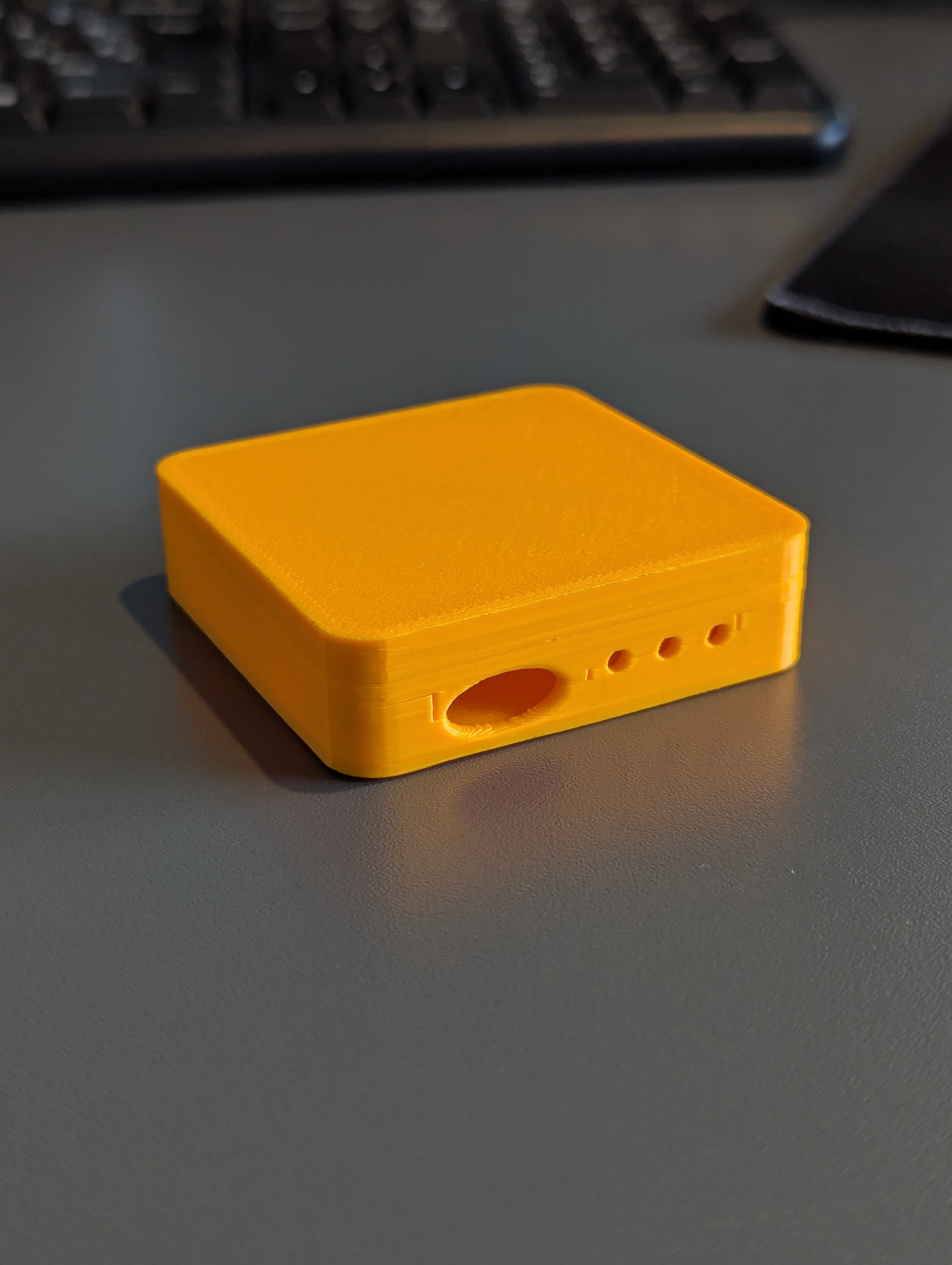
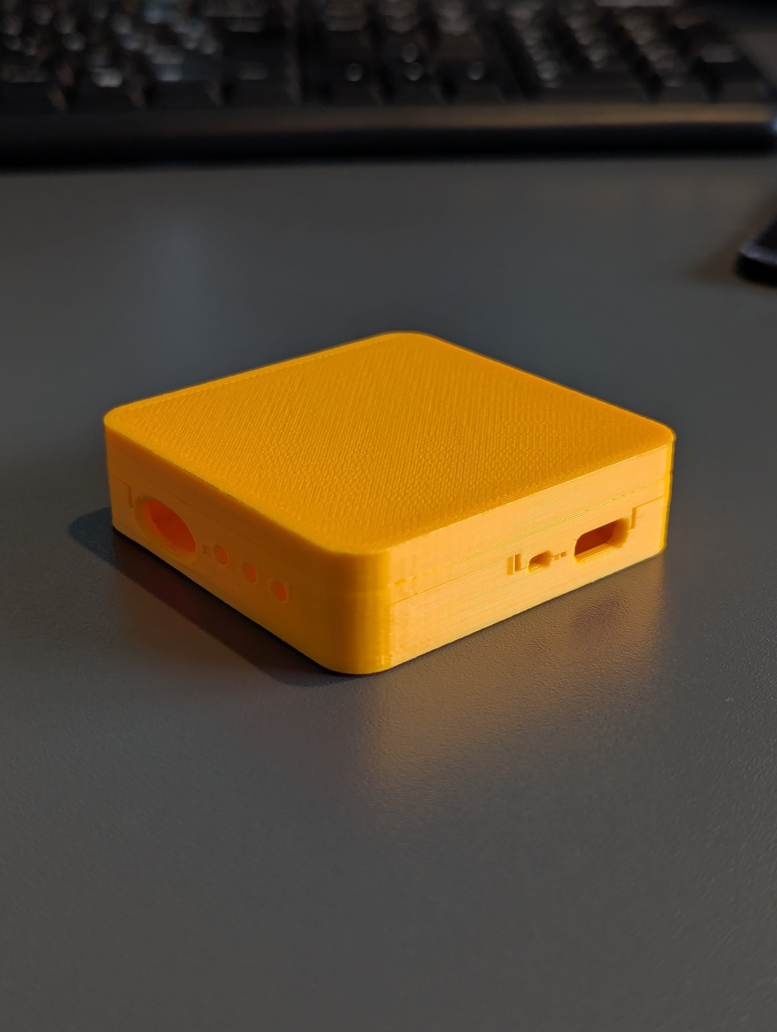
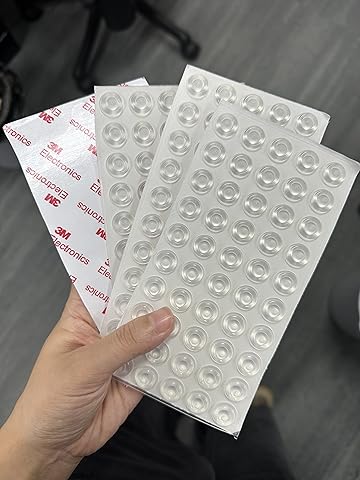
The last step of the process would be to attach four rubber feet to the bottom of the enclosure in order to prevent it from sliding off the surface. I haven’t decided on the type of rubber feet yet, but I’m thinking about using self-adhesive rubber feet that are commonly used for furniture if I could find them in the right size.
Future Plans
I don’t like how the Volume rotary knob is not sticking enough out of the enclosure, so I would like to make it stick out a bit more in the future. I haven’t managed to find a suitable knob with larger knob diameter and maybe a redesign of the PCB would be necessary. Maybe I can “extrude” the part of the PCB where the rotary knob is located so it sticks out more. I wouldn’t want to do that actually because I like the rectangular shape of the PCB. In order to make knob adjustment easier, I’ve made quite a large cutout so the thumb finger can easily reach the knob.

I’m thinking about spray painting the enclosure in the future in order to make it look more professional and to protect the PLA from UV light. Later, I would like to laser engrave the logo on the top part of the enclosure with the name of the project, and add labels for the LEDs and the Volume rotary knob. I presume that the laser would burn the spray paint and reveal the PLA color underneath.
Conclusion
I’m quite happy with the enclosure design and the way it turned out. The design is simple, clean, and functional. The assembly is easy and straightforward. I’m looking forward to testing the enclosure with the final version of the PCB and making any necessary adjustments
Note: If you’re interested, you can pre-order a sample at vnucec.ivan@gmail.com.
 Ivan Vnucec
Discussions
Become a Hackaday.io Member
Create an account to leave a comment. Already have an account? Log In.