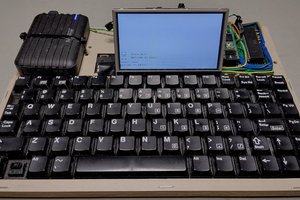
A Teensy 4.1 running as an Apple //e
To make the experience fit your profile, pick a username and tell us what interests you.
We found and based on your interests.
In 2017, I had a couple fundamental goals in mind when I build the first Aiie. It was a nice winter electronics distraction; it was very nostalgic; it gave me a better way to play games I used to enjoy, more or less the way I enjoyed them. But it also gave me a platform to extend beyond what I could do back in the 80s. To build in "hardware" I couldn't afford back then. And top of my curiosity list: the Mockingboard.
This sound card used AY-3 chips - a 3-voice square wave and noise generator with an envelope processor. Not as complex as the SID chip in the Commodore 64, which was a warm, organic sort of synth sound; this is instead a crisp, digital sort of synth. I never had one, so I never had opportunity to hear what they really sounded like. I lived with high frequency carriers driving the speaker with feedback, where the pulse stream density represented the complex waveform they were trying to generate (a process called delta modulation, where the Apple community uses the term "Binary Time Constant" or BTC). Very cool, and a very recognizable sound... but really CPU-intensive. You could see when games used it in their intro screens - like in Alternate Reality, where music is playing and screen animation only happens in the pauses between music (well choreographed to play like a dance between music and screen).
So I gave the Mockingboard a stab back around 2019 somewhere. I started by finding documentation on the AY-3 and trying to code an AY3.cpp module. I never got very far; it's fairly complex, and it wasn't clear how I would test that it was performing correctly. And I was sort of pigeonholing it into the role of a sound engine, instead of a general sample-rate fixed-point generator. On the shelf it went, until I decided to look at it again in April. After getting the audio buffering WSOLA driver working well, I wanted to hear what audio could have sounded like if I'd had the money around 1985.
Instead of trying to make a cycle-accurate hardware reproduction in software, I went for an approximation. I wired it in to the WSOLA layer of my SDL build, so I could test that things sounded right; and did a substantial amount of playing something in another emulator (mostly Virtual ][, still my go-to) and seeing if it sounded more or less the same as what i was generating.
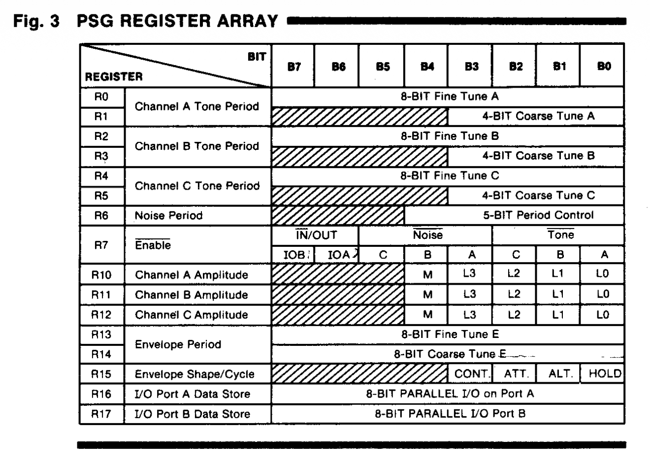
Starting from the inside and building out: the AY takes 16 register values and elapsed time, which are output as samples. The datasheet is still king:
From those, the output sample is: for each of 3 channels, if the gate is high, add a table-driven amplitude; sum; clamp. That's it, straightforward DAC. So I started by finding references for the 16-value amplitude table...
static const int16_t ayAmplitudes[16] = {
0x0000, 0x0034, 0x004B, 0x006D,
0x00A0, 0x00ED, 0x0152, 0x0223,
0x0292, 0x03C0, 0x04F2, 0x0710,
0x0906, 0x0B53, 0x0F13, 0x1FFF
};
Some notes here: this clamps at 0x1FFF (8191) so that 3 voices summed stay under 16 bits without overflowing. That peak made sense to me, but I'll admit this is about where I got stuck last time around, and it's not like I've spent significant time researching how the Mockingboard worked in the intervening years. No - my research here was in source code for other emulators. I needed something to get myself started so I looked at the AppleWin and KEGS source code. They both have tables too, and by reading the source and then trying to understand the data through the datasheet for the chip, I understood just about enough to wrap this in a .wav file generator that could give me the 16 (well, 15) sample amplitudes (volumes) represented in the table.
Also note here: I'm pretty sure I just calculated my numbers as a normalized log table. The datasheet's curve gave an approximate response, that's the ballpark I'm modeling here.
The chip's got 3 channels, so I need to mix them (add the values). And there's a noise generator (which I clearly modeled on the...
Read more »The Aiie project is designed as a set of core code wrapped by two front-ends: one for the Teensy, and one for the Mac (using SDL). That's because I need a way to test this stuff without spending a crazy amount of time slowly debugging on the Teensy hardware. It's great, and I love it, but a multi-minute reflash-and-test cycle is pretty long when I can do the majority of that work with a few-seconds-long rebuild-and-launch cycle directly on my laptop.
That same sense of urgency (or disquietude, I suppose) exists in the rest of the code base as well. It's why you can run the emulator at faster speeds: why wait for a 1MHz processor emulated, when I could run at 16MHz for something that would otherwise be a long task?
The answer would be, of course, because it no longer gives you the same experience. Sometimes that's not a problem (like waiting for Merlin-8 to load). Other times it's undesirable (like trying to play an arcade game, at 16x the normal speed: this is not the definition of speed run that you're looking for). But it's up to the operator to know which is right - and some times that faster emulator is really what you need.
One of the side effects, though, is that the Apple ]['s sound is based on clicking a speaker. Which means the frequency of the click is tied directly to the speed of the CPU; and if we speed up the CPU, the frequency of the sound it's playing will go up. I've lived with that for a long time; usually it means I get mousey "squeak!" instead of stately "Beep"s, or maybe a hearty "BOOP" if I'm running at half speed for some reason. That's not always the case, and while playing with the copy protected disk formats, I found myself listening to The Chipmunks (tm) playing the theme music for games on their splash screens.
Unacceptable, I tell you! We can't have this.
Posit: my waveform is dictated by the speed at which I put data into the waveform itself. I want to change the speed of putting data into the waveform, therefore it modifies the pitch. Imagine, for example, we have a 440 Hz sine wave (A4, the "middle A" on the piano, also the note that orchestras tune to - or at least we'll pretend that's true lest we go down a different rabbit hole) which I will represent with data thusly:
~~~~ ~~~~ ~~~~ ~~~~
We put the data in twice as fast, and the cycles are now closer together in time:
~~~~~~~~~~~~
so it plays back as 880 Hz - twice the pitch, or one octave above. We're now playing A5, the next A on the piano.
I vaguely know how to solve this problem with hardcore math. We could use Fourier transforms to analyze the sound, placing it in "bins" of what frequency it hears; shift the data, reconstruct it. That's my math-heavy engineering background that wants to do this really cool thing, because it's the hammer I use for frequency analysis. And it's the wrong tool here; it's fairly slow. This is a valid way to do it, though, and it's called a phase vocoder. That's 19th century math, applying 1970s transformation, reliably. Stoically, even. Time, frequency, amplitude, and phase become data you can manipulate.
In the 1980s, we developed Pitch-synchronous overlap-add (PSOLA) as part of speech synthesis research. Basically, speech is not just a waveform; it has repeating periods where the pitch is the same. You have
|---cycle---|---cycle---|---cycle---|
and if you manipulate those cycles directly, you can change the duration, pitch, and emphasis without losing the voice quality. WSOLA (Waveform Similarity and Overlap Add), instead of cutting at arbitrary locations, finds similar waveform regions. By mathematically correlating those regions, it determines where a waveform segment can be inserted, removed, or shifted while minimizing discontinuities. WSOLA preserves the natural "shape" of the waveform by ensuring that neighboring sections line up smoothly. It effectively stretches or compresses time by repeating or skipping sections of the waveform...
Read more »Hi! It's been a minute. As the kids say. Or said, a couple decades ago, or something.
Anyway, in that minute (seriously, 4 years?) a little bit rot set in, and in April I started righting it. The problem with picking up a project that has been asleep for years is that the world inexplicably did not stand still, waiting for me to open it back up. So I've brought this up to speed: the SDL build works under current MacOS (the compiler is pickier than it used to be), and the Teensy build has a new headless driver using the newer arduino-cli system. None of that is particularly interesting, but if I want to enjoy riding the horse, I've first got to shovel the ... stall out.
Disks, disks, disks: the Director's Cut
A while back I posted about the disk subsystem (Entry 14, in fact). And the reason I picked this back up in April was because, again, that subsystem was not quite working correctly. I'd built the driver around the general concept of the whole emulator: it's not important to run exactly the way the hardware did, but it is important to pretend that's the case. The difficulty is in figuring out where the blurry line of "yep that's important, but that's not" really sits.
In the case of the disk subsystem, for a long time it's been okay that it's been "mostly not the same" under the hood. I understand that, when something performs certain soft switch dances, it's really asking for the next byte off of the disk; so I provide it. The whole Entry 14 was about faking reality: making assumptions about what the caller is trying to accomplish, and getting it more or less correct enough that disks load.
But with .woz images that's not good enough; since the image is a reference for the magnetic flux and not the bytes on the disk, the emulation of the part of the drive that reads and interprets the flux data becomes important. In 2019 I got far enough that "standard" sorts of .woz disks worked as bit streams in Aiie. And now for copy-protected .woz disk images, it's really important that I emulate all the weird stuff that copy protection schemes took advantage of - it's not just a stream of bits on each track.
Half-track steps: a stepper motor (a motor designed to move in fixed increments, called 'steps') moved the read/write head along disks in the Disk ][ system; 4 steps to a track. So it's possible to move the head off of the "normal" track settings, and leave behind enough garbage on the "correct" tracks that the image doesn't copy quite correctly, while you position the "real" data in weird places.
Aligned track data across two tracks. Maybe your copy protection starts reading a track - say, track 3 - and a certain number of nybbles in to it, suddenly switches to track 4 and finishes reading from there. There are no "hard" sectors on the disk, so when you write a new track it starts from an arbitrary position (the sector markers are just magnetic data). If you make a sector-by-sector copy of this sort of disk, the tracks won't line up the same way that they orginally did, and reads will return the wrong data.
Weak bits - the read system on the Disk ][ expected a substantial positive or negative result; but it was possible to lay down a weak magnetic flux on the disk that is right at the border, such that reading that part of the disk gives you back random data. If you copy it, you wind up writing a definitive 1 or 0 on the copy rather than a bit that will randomly flop back and forth on successive reads.
This is the sort of stuff that you wouldn't normally expect, if you were designing something from an engineering perspective if you really wanted transportability and longevity. But here it is, sitting in a disk image that really needs all that kind of jazz.
In 2019, I built a utility named wozzle that could parse WOZ disk images, and convert between WOZ, DSK, PO, and NIB formats. There are other software packages that can do this but I needed...
Read more »As I've been writing in the last few updates: I've been working on support for the RA8875 display - so the next generation of the Aiie will have a display that can accommodate the 560 pixels wide that the Apple //e has in "double hi-res" modes (80-column text, double-low-res and double-hi-res graphics). That's all because without it, AIie has been doing some janky hacks to display those graphics modes on a panel that's only 320 pixels wide.
Most of what I'd think someone uses a handheld //e emulator for doesn't involve 80-column text, so until now I've sort of ignored the problem. It wasn't until I heard from Alexander Jacocks about how he was building an Aiie that the topic came back to the fore. I opened up a discord for us to chat, and we've been talking about what's lacking in the current build... and of course the display was the number one hot item.
We've spent a couple months talking about the hardware and software with a few other people that have also joined our discord, and (as I've written) we've got the 800x480 panel up and running at about 14 frames per second.
It's looking like we won't get past that point. We're pushing the display's (single) SPI bus as fast as it will go. It's possible that some hack can get a little more out of it (if we abandon the display outside of the "apple" screen area then it might be possible to only update the 560x192x2 pixels of the "Apple Screen"); and I've got some framework for only updating the parts of a screen that have been modified by the Apple emulator... but when all is said and done, if a full-screen game is updating the whole screen, there's not much you can do about the lack of bandwidth.
I think that's kinda okay. If I rebuild the PCB so it can accommodate either the ILI9341 320x240 display *or* the HA8875 driver from Adafruit with a 4.3" 800x480 display, then the user can choose -- do I want 30 frames per second with the smaller display and some graphics issues at higher resolution, or do I want all the pixels at half the speed? Putting the choice back to the builder feels like a reasonable trade-off to me.
Which brought me to the next crossroad. I don't want to abandon the folks that have already built an Aiie. The original Mk 1 is a dead end, unfortunately, because of lack of CPU to do what I wanted. But the Mk 2 has plenty of capacity and I really don't want the addition of a new display to strand folks; I still haven't taken advantage of everything those have to offer! How can I continue to support the Mk2 platform without having to fork the software?
Well, that's not too hard actually. Since there is plenty of space in the Teensy, it doesn't mind having two copies of the graphics and two display drivers built in. Take one of the unused pins from the Mk2, turn it in to a jumper or switch, and /Voila/ you've got selectable displays. Buy both if you want, and swap them as necessary. (This may not be ideal when we get to having an actual case, but for now at least it's plausible.)
From there I dropped back to the *nix variants of Aiie. I do most of my development and debugging on a Mac, using SDL libraries to abstract the windowing. It had been doubling the resolution of the ILI panel... but I've undone that. Now that the Teensy code supports two different displays with different resolutions, the SDL wrapper does the same... and when you're running it with the ILI ratio, it's natively 320x240 and not 640x480. Which means that, among other things, it became very ugly very quickly... and now this problem that has existed on Aiie since the start suddenly became a priority for me.
My first take at this was to logically "or" every two pixels together. If either of them is on, then the result is "on".
The text is sort of legible... but that white rectangle with the three dots in it is the letter 'a', inverted. As long as we're talking about black-on-white text it's... meh, probably okay.
Next up we have straight linear average: average...
Read more »I've been collaborating with a few individuals on Discord the last month or so. I've got bits of development and a lot of discussion going on over there, and if you're interested, drop on by. I don't know if this will work out long term but it's at least an interesting experiment...
Discord server invite: https://discord.gg/NRhMS6fRgZ
As part of the RA8875 display work, I had to build a new framebuffer and use the Teensy's eDMA system to automatically shuffle bytes out the SPI interface. In doing that I learned quite a lot about how the eDMA interface works, and what the magic code in the ILI9341 and ST7735 libraries does. I left a lot of those comments in my RA8875_t4.cpp module but I thought an out-of-band write-up would be really useful (for me for later, if not for others trying to do the same thing).
To begin with: download the IMXRT 1060 Manual from PJRC. The inner workings of all of this is documented in there, but it's not all in one place and can take a while to find (in the 1100-whatever pages of documentation). Eventually you'll be looking for data from it.
For me, the general path of getting this all working was:
The display initialization and LCD workings I'm not going to talk about too much - mostly it was a combination of looking at the RA8875 module distributed with Teensyduino 1.56 and looking up constants in the official display manual. The same is true of synchronous transfers -- a lot of copy/paste/delete/rewrite as I began to understand how the display itself works.
The framebuffer code itself is pretty straightforward. I needed an array for 8bpp 800x480, and declaring it is relatively straightforward:
DMAMEM uint8_t dmaBuffer[RA8875_HEIGHT][RA8875_WIDTH] __attribute__((aligned(32)));
A refresher from my last log entry: DMAMEM tells the Teensy to put it in RAM2, which is perfect for DMA to use; the height and width constants are 800 and 480 respectively. That just leaves the attribute, which is important for DMA -- it can apparently be picky about the alignment of the buffer it's copying out of. (I didn't have any problems with this, but then again I was forewarned and added the attribute. YMMV.)
From there it's just a matter of doing some pixel math -- whenever something needs to be drawn to the screen, calculate the proper index in to the array and store the pixel instead of pushing a command to the LCD to do the same work. Taking that buffer of data and feeding it to a synchronous update proves that I know how to interact with the display itself - initializing its display window, starting a new SPI transaction, telling it I'm sending memory data, and ending the transaction when done. Nothing difficult so far, just very very slow to perform its work. This is how I'd transfer all of the data to the display in a synchronous function:
_writeRegister(RA8875_CURV0, 0);
_writeRegister(RA8875_CURV0+1, 0);
_writeRegister(RA8875_CURH0, 0);
_writeRegister(RA8875_CURH0+1, 0);
// Start it sending data
writeCommand(RA8875_MRWC);
_startSend();
_pspi->transfer(RA8875_DATAWRITE);
for (int idx=0; idx<800*480; idx++) {
_pspi->transfer(dmaBuffer[idx]);
}
_endSend();
Those first four writes tell the display we're starting in the upper-left corner (Vertical and Horizontal cursor position at 0). Then send a memory write command; begin an SPI transaction with _startSend(); tell the display we're going to stream the pixel data; actually stream te pixel data; then end the transaction and we're done.
All we have to do is repeat that from a DMA handler!
Arr, but here there be dragons. Or maybe that's the wrong metaphor. Here there be performers of the dark arts? Certainly poorly documented capabilities that are hard to figure out from scratch. Which is why I leaned a lot on the ILI and ST code.
A lot of the...
Read more »When I was a freshman at university studying electrical engineering, one of my professors laid this out pretty plainly for us: engineering tolerance is important. If you're designing a system that needs 1 amp of current, your power supply better support at least 2 amps. You want room for failure - particularly when you're first designing something and have no idea how all the pieces will interact.
That often means that, if you know what you're doing, you can push past the stated limits of systems as long as you're willing to accept some risks. In the last log entry, you saw me push a 20MHz SPI bus over 26 MHz before it broke. Will every copy of that display get 26 MHz? I don't know, but it's possible. Will something be damaged by pushing it that far? Possibly, but it's not likely (in this case).
In the quest to get beyond 7 frames per second, this is the realm I'm visiting. What kinds of limits can I bend or break, without causing any significant damage? is there a way to get an 800x480 SPI display over 12 frames per second? Or maybe as far as 30 frames per second?
The first step is to consult ye olde manuals. What are the variables here and how do they interplay?
We've got the SPI bus speed. On the Teensy side of things, I see reports of people getting that up to 80 MHz. I've certainly driven it up to 50 MHz. We're not near those potential maximums yet - and the current failure is on the RA8875 side anyway. So what are the limits there?
According to the RA8875 specification, page 62, the SPI clock is governed by the System Clock - where the SPI clock frequency maximum is the system clock divided by 3 (for writes) or divided by 6 (for reads). The system clock, in turn, is governed by the PLL configuration that's set via PLL control registers 1 and 2 (p. 39). The PLL's input frequency is the external crystal (on the Adafruit board that's 20MHz), and twiddling PLLDIVM, PLLDIVN, and PLLDIVK configures the multipliers and dividers for the PLL to generate its final frequency.
The system clock frequency is
SYS_CLK = FIN * ( PLLDIVN [4:0] +1 ) / (( PLLDIVM+1 ) * ( 2^PLLDIVK [2:0] ))
and looking at the DC Characteristic Table on page 174, we see that it's "typically" 20-30 MHz with a max of 60 MHz.
Now, the RA8875 driver (as distributed with the Teensy) sets all of this as PLLC1 = 0x0B and PLLC2 = 0x02, which means sys_clk is 60MHz. Right at the maximum limit specified in the datasheet.
Will it go faster? If we make it go faster, what else will be affected?
Looking for all of the references to the system clock, I see that the two PWMs use it. PWM1 is being used to drive the backlight, so that might be important at some point, but probably isn't critical. More importantly: the pixel clock is derived from the system clock.
The pixel clock is how the data is being driven out to the display. While I see various generalities about the pixel clock required for different sized displays that suggests 30-33MHz for a 800x480 display, I don't have the numbers for the actual display I'm using. And looking at the RA8875 manual and doing the math, it looks like the pixel clock is actually 15MHz here, so those "normal" values are either unimportant or wrong. Either way there's not much to do be done about it until we understand more of what's going on.
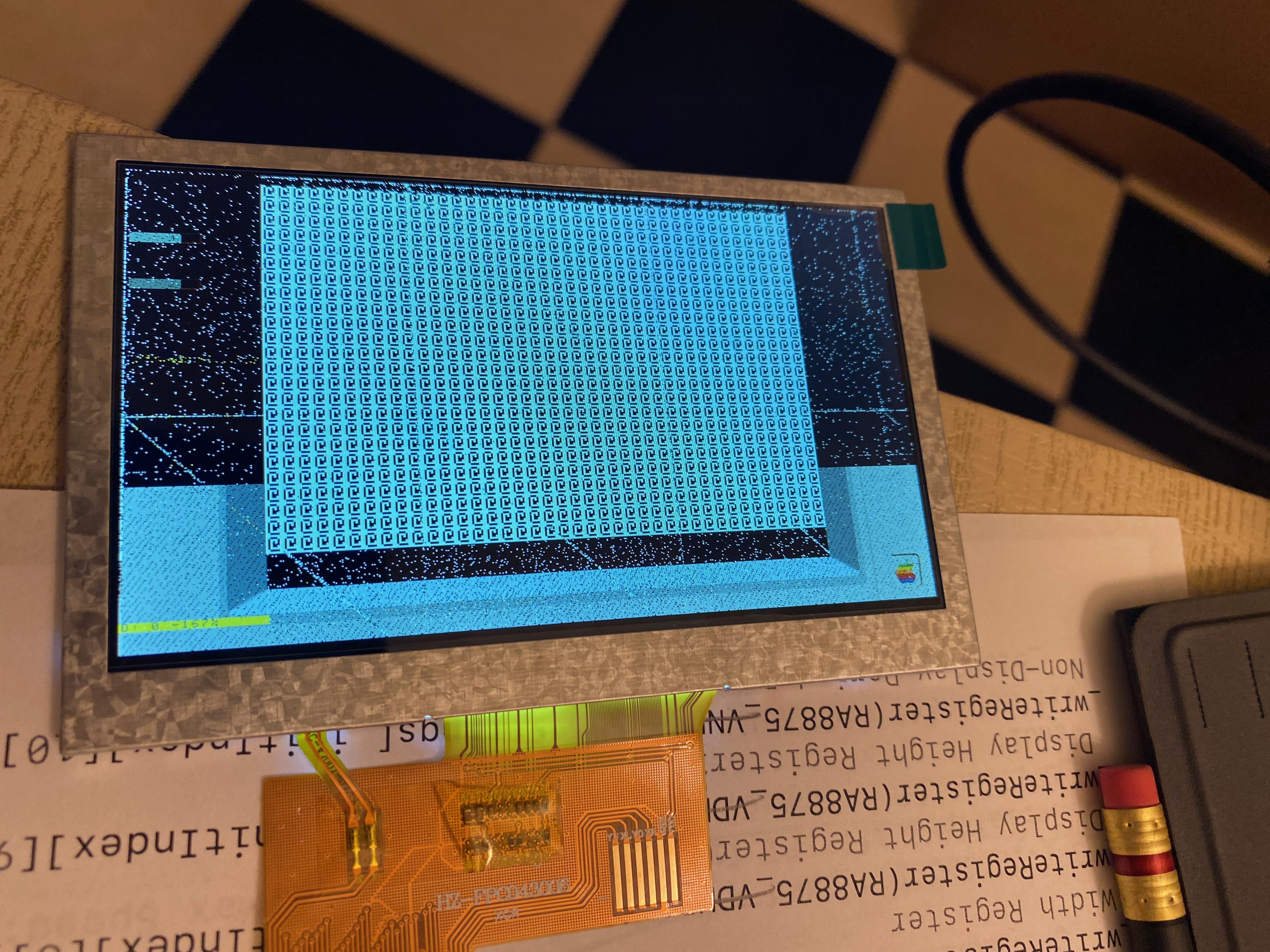
So, let's jump in the deep end! What happens if we maximize PLLDIVN (set it to 31), minimize PLLDIVM (set it to 0) and minimize PLLDIVK (set it to 0 also)? Short answer: nothing. A black screen. So we can't just set it all the way to the maximum. But a little bit of binary searching shows that we can actually set it to other values in the middle and it works with our 26MHz SPI bus just fine, and a sys_clk that's over 60MHz. How far? As far as 150MHz. Along the way I found that the display would break down in very interesting ways... like this, when pushing the SPI bus faster than the clock wanted:
Or this, when the pixel clock started drifting too far out from what...
Read more »_Alternate title: "BRING ON THE HACKS"... strap in, it's gonna be a ride.
When we started brainstorming about Aiie! v10, one of the first questions asked was, "why can't we just use an 800x600 display and show the whole display instead of hacking around it on a 320x240 display?"
What a lovely, simple, innocuous question. And oh boy what a road it's been.
Let's start with the physical... what 800x600-like displays exist for embedded systems? There aren't many, and they tend to be fairly pricey. There are NTSC, VGA, and HDMI panels (obviously requiring those kinds of output from your project, which I don't have; I've toyed with NTSC and VGA so either of those would be feasible). If I'm looking for SPI, though - there is basically just the RA8875 chip which supports 800x600 and 800x480, which are both good resolutions for Aiie v10 as discussed in my last log entry.
I'd like this to be as cheap as possible, though. Which means understanding the parts really well and ultimately deciding if I'm using someone else's carrier board or making my own. The 800x480 40-pin displays are cheaper than the 800x600 displays. And buydisplay.com has them for under $18.
So some digging later, I'd bought a 4.3" 800x480 display from buydisplay.com. Yes, it's cheap... but doesn't include the RA8875 driver. Pair it with the $40 Adafruit RA8875 driver board and we should be good to go. Can I make this display work in any reasonable way?
Well, maybe. Let's look at the software side. There is an RA8875 driver for the Teensy, that's good! But it doesn't support DMA transfers to the SPI bus. That's bad.
What exactly does that mean? It means excruciatingly slow screen draws. Like, 1 frame every 6 seconds if we're drawing one pixel at a time. This is the actual RA8875 drawing that way...
That may be terrible, but it gets worse.
The first version of Aiie used a similar direct-draw model and was always fighting for enough (Teensy) CPU time to emulate the (Apple) CPU in real-time, because it was spending so much time sending data to the display. Not to mention the real-time requirements of Apple 1-bit sound. It was a bad enough set of conflicts that I added a configuration option at some point to either prioritize the audio or the display; you could have good audio or good video but not both. And if you picked video, then the CPU was running in bursts significantly faster than the normal CPU followed by a total pause while the display updated.
All of that was solved when I converted to a DMA-driven SPI display. The background DMA transfers don't interfere with the CPU or sound infrastructure at all. So I definitely, absolutely, completely want to use eDMA-to-SPI transfers to avoid this bucket of grossness.
So let's start somewhere real... let's change teensy-display.cpp so it will be able to drive this thing, and see how it goes. Here's one line that's a great starting place in teensy-display.cpp:
DMAMEM uint16_t dmaBuffer[TEENSYDISPLAY_HEIGHT][TEENSYDISPLAY_WIDTH];
That's the memory buffer where the display data is stored. TEENSYDISPLAY_HEIGHT and WIDTH are 320 and 240, respectively - matching the 16-bit display v9 uses. The DMA driver for the ILI9341 automagically picks up changes there and squirts them over SPI to the display at 40-ish frames per second.
What happens when we change TEENSYDISPLAY_HEIGHT and TEENSYDISPLAY_WIDTH to be 800x480 instead of 320x240? We get our first disappointment, that's what!
arm-none-eabi/bin/ld: region `RAM' overflowed by 450688 bytes
Simply put, there just isn't enough memory on the Teensy to be able to hold the display data. Let's dive in to that a bit.
The Apple //e has 128k of RAM. The Teensy 4.1 has 1MB of RAM. I would seem, on the face of it, that there should be enough RAM for a 480x480x16-bit display buffer - that's 750k. Yes, there's more overhead in the rest of Aiie... but a rough calculation says that for us...
Read more »In 2021, a friend of mine gave me an Apple //e that he'd had sitting in a garage for years. He'd rescued it from a place where another one of my friends had been working, probably around 1996. I've spent a few months cleaning and fixing it up; part of that effort lead me to build the Apple ProFile 10MB Hard Drive reader. It's also gotten me playing Nor Archaist - which my wife bought me for Christmas 2020 - on the actual //e.
But that's not what I'm here to write about. I'm here to write about how all of this pushed me back to working on Aiie!
Just as I was thinking about how the //e was going to come back together, someone reached out to me on Twitter with questions about their own Aiie v9 build. Some of the components are no longer avaialble. I never listed why I picked the voltage regulator circuit I'd used (because it's a 1A boost). The PCB pads for the battery aren't labeled (J6 is +B and J5 is GND, but I'd left it flexible for the boost circuit). The version of HDDRVR.BIN (from AppleWin) has changed. The parallel card ROM is one of a pair, so if you have the actual card, it's not clear which one to dump (it's the Apple Parallel ROM, not the Centronix ROM).
This all got us talking about what else I'd forgotten to finish (sigh, woz disk support; Mockingboard emulation; WiFi). And then we started talking about what else we could do with a new revision of the hardware. Design a case, maybe. Update the parts list. Integrate a charger.
And update the display.
Now, most of that was on my roadmap... but I'd convinced myself to forget completely about the display. It's a hack that I'd optimized and considered "done."
The display on the Aiie! v9 is a 320x240 SPI display (the ILI9341). It's the second display I've used for this project. The original was a parallel interface that required a lot of CPU time to drive; I think I managed to get it up around 12 frames per second. The SPI interface for the ILI9341 not only uses fewer pins, but it can also be run directly from the Teensy's eDMA (extended? expanded? direct memory access) hardware, directly sending the data out the SPI bus without the program manually doing the work. eDMA does a block transfer; when it ends, it automatically starts another one. The frame rate went through the roof. I think I saw it up around 40fps... where anything over 30 is overkill. (Hmmm... the black magic of the ARM IMXRT 1062 eDMA system would be a good topic for another log entry...)
Fine, that explains why I chose an SPI bus driven display. But why is the display resolution 320x240?
The Apple II video is really low resolution. The plain text screens are 40x24 characters, where each character is 7 pixels wide and 8 pixels tall - resulting in a 280x192 display. Lo-res graphics chop each character vertically in half, giving you 40x48 blobs that use 280x192 pixels. Hi-res graphics are, not surprisingly, 280x192 pixels. Fits fine in a 320x240 display, no problem! They're cheap, one's for sale right at PJRC along side the Teensy, and it's got a well supported driver that's been optimized by the Teensy community. It's a slam dunk
But with the //e's 80-column card, Apple made it weird. (I know, that's not a big stretch. The whole machine is built around engineering miracles, which is part of what I find so endearing.)
In 80-column mode, the horizontal resolution doubles but the vertical does not. Basically data gets shoveled out the NTSC (or PAL) generator twice as fast so it's twice as dense - but the number of scan lines aren't affected. So you wind up with the really awkward 560x192 pixel size for 80-column text, double-low-resolution, and double-high-resolution graphics.
So I wrote the core of Aiie! to support 560x192. There are three builds of the core code - one for SDL (which is what I primarily use for development under MacOS); one for a Linux framebuffer (which I've used in passing on a RaspPi Zero as a toy); and the Teensy build for my custom hardware. Under SDL and the framebuffer,...
Read more »On my list for a good while has been mouse support - mostly because I'd like to add networking support, but most of the programs that have Uthernet card support (which is what I want to emulate) also require a mouse card. So, quite some time ago I started working on the mouse for Aiie, and was stymied with the lack of CPU power on the Teensy 3 (mostly architectural, based on how I'd designed it).
With the Teensy 4.1 running the show, things are looking pretty good - I'm running the CPU at 396 MHz, downclocked from the stock 600 Mhz and well lower than the 816 MHz it can run at without cooling... so I shouldn't have any problems there. Which means it's just a matter of time and understanding.
The time has presented itself, and here's the understanding. Let's start with how the mouse works on the //e.
The AppleMouse II was the same mouse used on the Mac 128/512/Plus. The card it used on the //e interfaced with the system bus via a 6521 PIA ("Peripheral Interface Adapter") chip. It was glued together with a fairly substantial ROM, which not only used the standard 256 bytes of peripheral card space but also page-swapped in another 2k of extended ROM on demand.
My first thought was to implement a soft 6521 and glue it in to the bus; then use the real ROM images to provide a driver. It seemed a tedious, but likely robust, way to build it out.
The 6521 code wasn't hard to write, but testing it is a different story; the only way I have of testing it is by booting something that has mouse support, and seeing what happens. Which means blindly interfacing the mouse card on top of the untested 6521, and figuring out which problems are bugs in the 6521 vs. which are problems in my interface to the program running on the Aiie.
I figured that GEOS would be a good way to test the mouse itself. I'd used GEOS back in the 80s, so I knew what to expect - particularly that it used quite a lot of what the Apple //e was capable of back in the day. Double-high-res graphics, all 128k of RAM, all on top of PRODOS. But when I booted it, the mouse didn't work, and I couldn't quite figure out how to debug it.
Which is approximately where I put it down in 2019, waiting for some stroke of inspiration. Or fortitude.
So when I picked up the mouse driver again, I wanted to do it another way. I've spent some time bringing the SDL build up to snuff, working from the same code base as the Teensy 4.1 so I can directly debug on my Mac. So to find out how the mouse was supposed to work, I started reading all the AppleMouse documentation I could find.
Which isn't much. There's the AppleMouse II User's Manual; the related Addendum; a smattering of old usenet (as far as I can tell) the exists in various forms around the Internet. A few other dribs and drabs but nothing substantial.
At that point, I figured I'd start disassembling the original ROM and building my own. But I had some substantial questions.
I'd already decided I'd put the mouse in slot 4, so booting up the machine it's straightforward to look at the basic 256 bytes of ROM directly in the system monitor as disassembly or raw data. I went for disassembly.
] CALL -151 * C400L
But this was all built in the days before anyone had hardware you could interrogate - there's no handshake to ask the board what it is, so it's not the code that's important right now. The OS detected the hardware by reading bytes out of its ROM and guessing at what made it a mouse. Over years of hardware appearing, patterns emerged and it became standard practice to look for certain fingerprints of data. Eventually Apple released the 1988 specification "Pascal 1.1 Firmware Protocol ID Bytes". It says that the bytes at offsets $05, $07, and $0B must be $38, $18, and $01 respectively. And all of that is true in this firmware. It also says that byte at offset $0C is the hardware identifier - in this case, its value is $20....
Read more »
Create an account to leave a comment. Already have an account? Log In.
nice job! But is it possible to run this code with stm32f429 at 180MHz ?
small keyboard idea - maybe you could take one from an old pda/phone case - eg tungsten W or treo 650, or a "snapNtype" minikeyboard made to slide onto a palm m500 etc? regards
As it happens, there's a blog post today for that: https://hackaday.com/2018/03/08/regrowing-a-blackberry-from-the-keyboard-out/ Something like this would be perfect for this project.
Thanks heaps for Aiie. You inspired me to create the Game Bloke. All my retro-apple gaming needs are now fulfilled no matter where I find myself.
http://github.com/prickle/GameBloke
It's perfect! Except for it's unfinished, it still has memory issues, and it's hacked, worm-ridden code is no longer compatible with Aiie.
I might suggest Save/Restore State and Atari Joyport emulation is worth having although I doubt my implementation is of any use to you as is. My bloated keyboard class is responsible for joystick activity. Lots of hacks throughout give things like more efficient menus and file browsing, faster NIB file loading, all basic stuff but too numerous to recall.
I can browse my whole collection, load and run most of it and play most of that. Most satisfactory.
Cheers!
That's fantastic! Well done. :)
I've definitely got designs on a save/restore state for Aiie - I just need the time to finish implementing it. Right now it's all tied up in a Dalek build that has to be done soon; I expect I'll be back to Aiie work in December.
Aiie is working very nicely for me. Good job! The USB keyboard mod I added appears to work fine. I am still having RAM issues though.
Would removing Mockingboard constants add much free RAM? Mockingboard is already disincluded. I also disincluded parallel and that didn't seem to help much. I guess the reason the memory is gone is because I am using different library versions, probably newer and bigger. Adding the USB library also used loads of ram and now I'm way short.
Is it possible to emulate a 48k apple instead of 128k?
You can pull my latest code from github; I moved the mockingboard stuff in to a branch while it's in development.
You can also go to the BIOS -> Debug, which has an option "show mem free". If that's on while it's running you'll see numbers down at the bottom of the screen - an estimate of free RAM, and the current heap size.
It's certainly possible to make this emulate a 48k Apple ][; doing that would need some code changes to undo a lot of the //e-specific functionality.
Hmm. Perhaps I don't want to go all the way back to an apple II. Lots of games won't run, no Prodos etc. I need to free up about 32k.. Could I leave out, say, the language card without breaking too much software? What could I sacrifice without losing too much functionality?
I don't know that there's much between a 48k Apple ][ and a 128k //e. What's eating the extra 32k? Is that the USB code?
It seems my display backlight does not like being run directly off 5v as it gets rather hot and bothered, enough to cook a black blotch into the LCD after a while. I notice the SainSmart Mega Shield runs the backlight off 3.3v but it might tax the Teensy's regulator doing that. I think I will try a current limiting resistor off 5v to my backlight to see if I can cool it down a bit. Perhaps 47R wouldn't loose too much brightness? Any idea the current draw?
Not offhand. You might throw a 1n4001 or similar inline.
Is this a SainSmart you're using? eBay or direct?
The SainSmart docs for their TFT (http://sainsmart.com/skin/frontend/base/default/document/3_2%20inch%20TFT%20with%20SD%20and%20Touch%20Quickstart.pdf) say LEDA+ is driven @ 5v, but don't mention the current draw.
SainSmart I think, Ebay? It's old and has been in a drawer for years. Looks a lot like yours. 47R series resistor worked well, it is now runs cold but it looks like one of the LEDs didn't survive. It seems the display backlight has no current limiting on board. Oops, didn't think to check. Never mind, the display was already somewhat damaged in other ways and still works well enough for development. Just a warning for other makers.
Now I am having troubles with uSDFS. The call to g_filemanager->readTrack() on line 447 of diskii.cpp is not returning. The uSDFS library is being quite uncooperative.. perhaps my SD is formatted wrong? Or the uSDFS version I got is buggy? Or I broke something while hacking on the code? Don't know yet. It was a bit tricky getting it to compile in Windows and yes, I flattened the directories, sorry :-)
(Edit) Actually, I now think I am out of memory. Drilling down reveals the malloc(4096) on line 22 of diskii.cpp is returning null. Reducing this to 2048 allows it to allocate but of course crashes later. Any easy way to free up a couple of k?
You could rip out some of the Mockingboard-related constants, like all of SSI263Phonemes.h. None of that is done, and I think I'm going to have to abandon it; there's just not enough CPU to drive both the display and a Mockingboard.
But it seems odd that you're out of memory when I'm not. I'm not sure why that would be...
Ok, I have built working hardware but I'm not sure what to put on the SD card. What does Aiie expect in terms of directory layout and file formats?
It just expects disk images.
Anything .dsk or .DSK is a DOS disk image; .po or .PO is a ProDOS image. I think there's a hard-coded disk image being loaded at startup in teensy.ino - something I should remove from the code. Until then you can just "Cold Reboot" and then insert a new image in drive 1.
This is a really nice project. I appear to have most of the hardware but thats just too many tact switches for me. Have you considered using the USB host for a simpler keyboard interface? I believe a C64 emulator is being developed for the Teensy that uses this approach.
Interesting idea. The Teensy is really bogged down driving the video display. I wonder how much worse it would be if it were also using the USB host and a keyboard. I'll have to poke at it a bit...
I'm going to try it soon as my hardware targets this approach, I just need to tackle the key mapping from Teensy USB library to aiie. Currently the modifiers (shift, ctl..) do not generate their own up/down events. I think we want this, so next step is fork and modify the USB library.
Love your build, however I would not want to tackle such with my transistors and diodes ;-)
It looks like a great project! I wonder if it could be made to emulate an Atari 800? ;)
There were a couple of things I was wondering about. You said you didn't need diodes in they keyboard because of the way the Arduino keypad library works. I've been using that same library for the NanoEgg synth and very much need the diodes, so I was wondering what you might be doing differently than I.
Also, I made some revisions to the keypad library for better real-time key event processing. That version of the library lives here (I'm not sure why somebody else decided to put a fork someplace else.) https://github.com/Nullkraft/Keypad
I'm really curious about your parallel screen interface stuff. I was using the PJRC TFT touch screen and have had real troubles getting a decent frame rate out of it. Even overclocked, I've only got up to 44 FPS on the Teensy 3.6. Furthermore, having no vertical sync signal means I can see tearing when the display updates. So your parallel access solution interests me greatly.
I'm hoping your source code will be available someday soon!
The Atari 800 might be a little too fast for this as-is. But maybe not, I've never tried.
Are you using an old version of the keypad library? I saw that, at some point, they weren't tri-stating the lines - which means you would have needed the diodes.
I have tearing in the current screen implementation too. The original didn't, only because it was throttling back the CPU in favor of the screen updates (and then running extra CPU cycles to make up the time).
The source code is all over on github! Have at it - https://github.com/JorjBauer/aiie
That's what i need on these days. Probably i have all of these components, some 6502 assembly knowledge and retro computer curiosity. Can i get schematics?
Hey! Really nice project you got there!
Could it run an OS like Kali Linux? or Kali NetHunter?
You could probably get a version of uCLinux to run on it, but it would be a lot of work. And I'm not sure you'd be able to do anything particularly useful with it. I mean, certainly it won't play Skyfox like the Apple //e emulator will. ;)
This is nice but I prefer a standard notebook size running 65C02 (like an Apple IIc but more portable) with dual floppy drive built-in !
Ah yes. But I couldn't build one of those with parts in my basement...
Thanks! I've gotten myself sidetracked with Mockingboard support. I'm about half done...
Become a member to follow this project and never miss any updates
Samuel A. Falvo II
ziggurat29
Jorj Bauer
it can run fuzix os ?