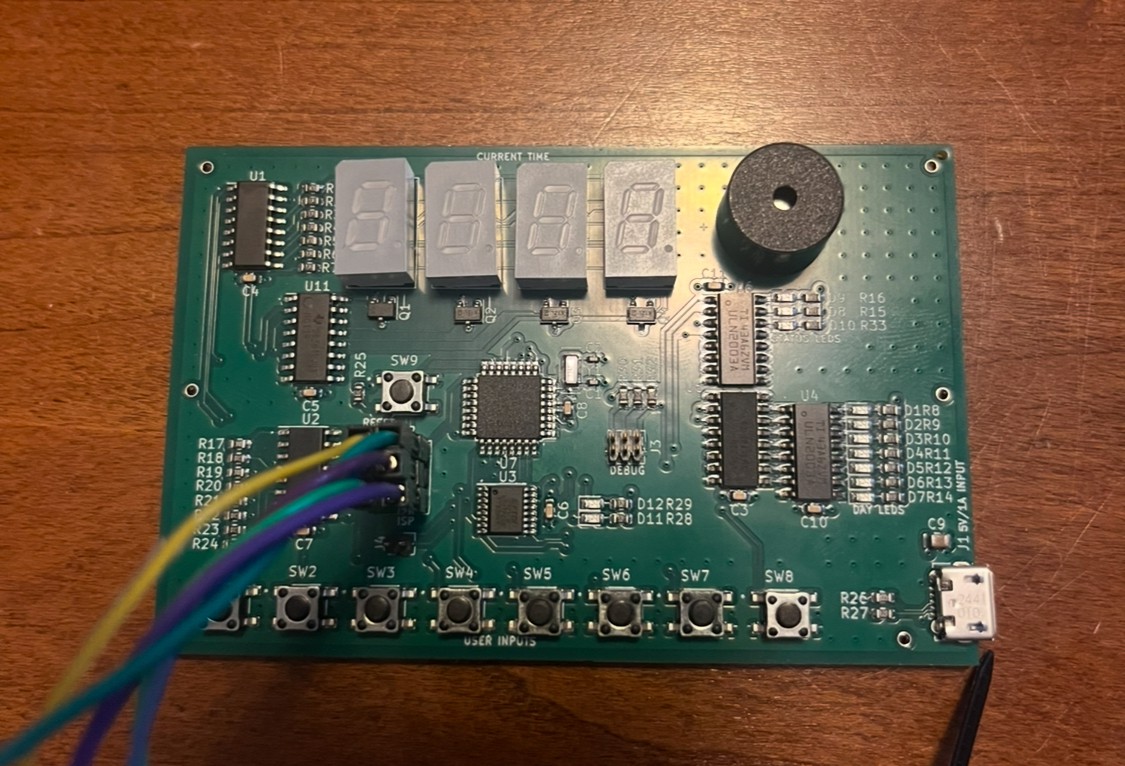
I received 2 assembled PCBs earlier from JLCPCB this week and have been toying around with the board's various peripherals. Everything seems to work as intended, thankfully - I'm always a bit worried about my PCBs not coming out how I intended. In fact, the PCBs look great:

The good news is that the FTDI FT230X USB-to-serial converter on the PCB works very well and responds , despite me accidentally using the wrong resistors specified (22 ohm vs 27 ohm), neglecting to use the capacitors they specified, and relying on the 8 MHz internal oscillator on the ATmega328PB. The USB power interface works - nothing to report more there.
The interface to the ULN2003 load drivers seems to work flawlessly - before anyone says "but the ULN2003 is old and outdated!", I used them solely because JLCPCB classifies them as a basic part without additional setup costs. The LEDs (and the 74HC238 glue logic for day selection) work well and are reasonably bright.
The seven-segment driver hardware I put together also works very well - the 74LS47 and a series of 4 PMOS transistors driven by a 74HC139 are responsive and respond well to the scan algorithm executed by the ATmega328PB. Right now, a 50 Hz refresh rate is being used and results in no visual discontinuities.
It took some tinkering, but the 4021 shift-register interface for the 8 user input buttons is implemented and uses some NOP commands to ensure that the datasheet delay times are being respected. What is unfortunate is that routing challenges resulted in SW1 not matching up to bit 0 on the shift register, but things like this are easily fixed in software.
The Timer2 overflow interrupt driven by the 32 kHz crystal results in a near-perfect 1 second interrupt interval as configured. I've previously experienced some minor annoyances trying to do the same on a PIC16LF1823 due to the 16-bit timer register there and slow PIC CPU operation throwing off the timing slightly.
I wrote a test program to activate the buzzer with a variable Timer1 output and it's just loud enough for this application. I still have to work on a proper frequency to get that working how I want it to.
I've been using avr-gcc + MPLAB X with a PICkit 5 (configured for the ISP interface) for development and have experienced no issues so far.
I wrote a test program to implement a basic clock with 24HR/AM/PM modes implemented as well as some buttons to change the minutes/hours/day of the week. Day of the week is implemented and will rollover when the hour counter hits 24. I set the clock, left it on the entire night, and returned to find it was keeping time throughout the night.

Next, I will have to implement the alarm clock function - which appears to be a challenging part due to the UX considerations.
I've uploaded the (so far) source code to the project page for anyone who wants to read it.
 Zachary Murtishi
Discussions
Become a Hackaday.io Member
Create an account to leave a comment. Already have an account? Log In.