My vision for iCamMini is for a remotely accessed camera. For example to be flown on a drone or remotely operated vehicle or to be mounted (suitably protected) outdoors or on a lab bench monitoring a circuit while the user sits at a computer. The video interface can be connected to a long-range transmitter or the camera can be accessed via Wi-Fi for shorter range applications.
The prototype consists of a baseboard I designed called iCamCtrl and a Tiny1C breakout board. I didn't originally design-in a RTC chip so a PCF85063-based breakout from Seeed Studio was added and I directly soldered the AHT20 and VL53L4CX breakouts to the Tiny1C board.
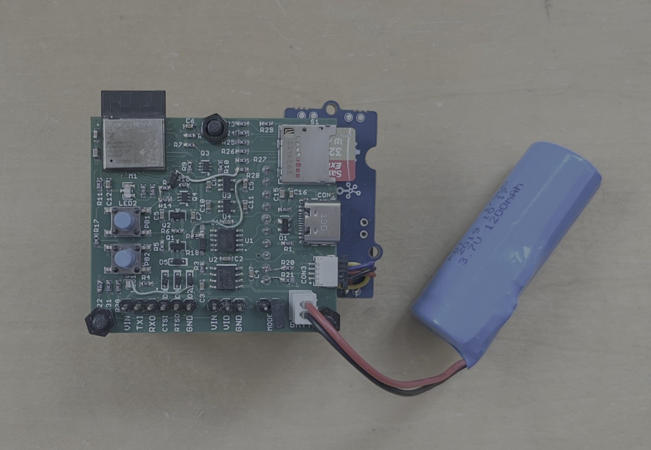
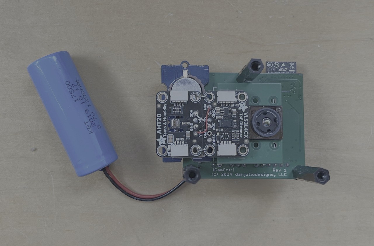
It utilizes a ESP32 Pico module with 8 MB Flash and 2 MB PSRAM.
Block Diagram
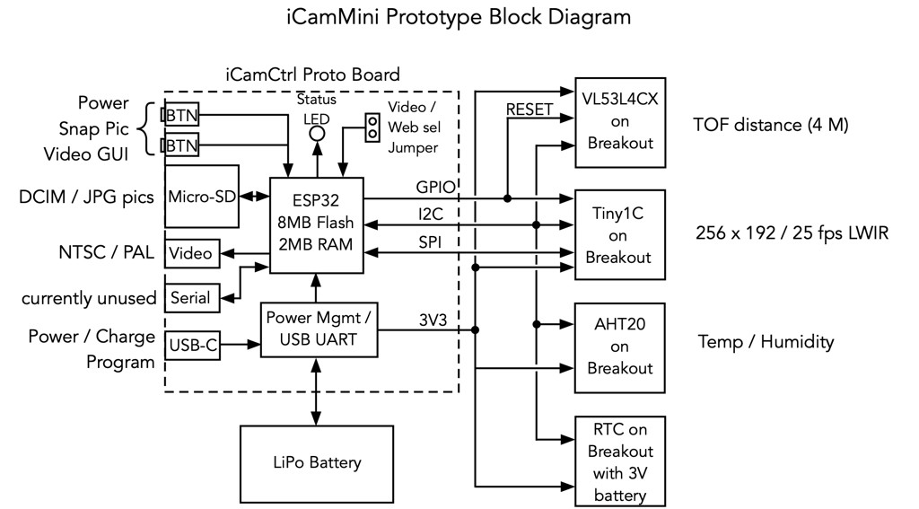
I'm currently designing a Rev 2 that fixes some issues and integrates the RTC and backup battery.
iCamMini has several hardware interfaces.
- USB-C for power/charging and programming via a CH340K USB UART.
- Video Output
- CMOS Serial port with flow-control. Currently this is unused.
It can be powered from a variety of sources
- USB-C
- 3.7V Li-Po battery
- 5V through the video output port
- 5V through the serial port
All inputs are reverse diode protected and multiple can be powered simultaneously without reverse flow. The idea is to make the camera easily powered by other devices, for example a video transmitter might output 5V for the analog camera.
A jumper, sampled at boot, selects between Wi-Fi or Video mode.
It has two LEDs and two multi-function push-buttons for local control. The push buttons are used to control power, take a picture (stored as a JPG file in the local Micro-SD card), reset the Wi-Fi to default settings and control setting some camera parameters when the video output is active. One LED indicates charge mode (directly controlled by the TP4056 charger controller IC) and the other, red/green LED indicates various status or fault conditions under control of the ESP32.
Soft Power Control
Soft power control allows firmware to shut down the camera (for example for a critically low battery condition). It is implemented using a pair of P-channel MOSFETs that act as a high-side switch between incoming power and the internal 3.3V regulators. One is switched on whenever one of the push buttons is pressed. The other is switched on under control of the ESP32. The user presses the power button and the ESP32 starts to boot. The first thing firmware does after booting is to switch the other MOSFET on and then light the LED to indicate to the user power is on. Then the user can let go of the power button. This takes a fraction of a second. The ESP32 can also sense the state of the push button so it can detect a long-press (or other software command) to switch off power and turn off the second MOSFET (after waiting for the switch to be released). A side-effect of this method is that the power button has to be held closed while loading firmware.
The other button is a purely software read peripheral.
Wi-Fi Mode GUI
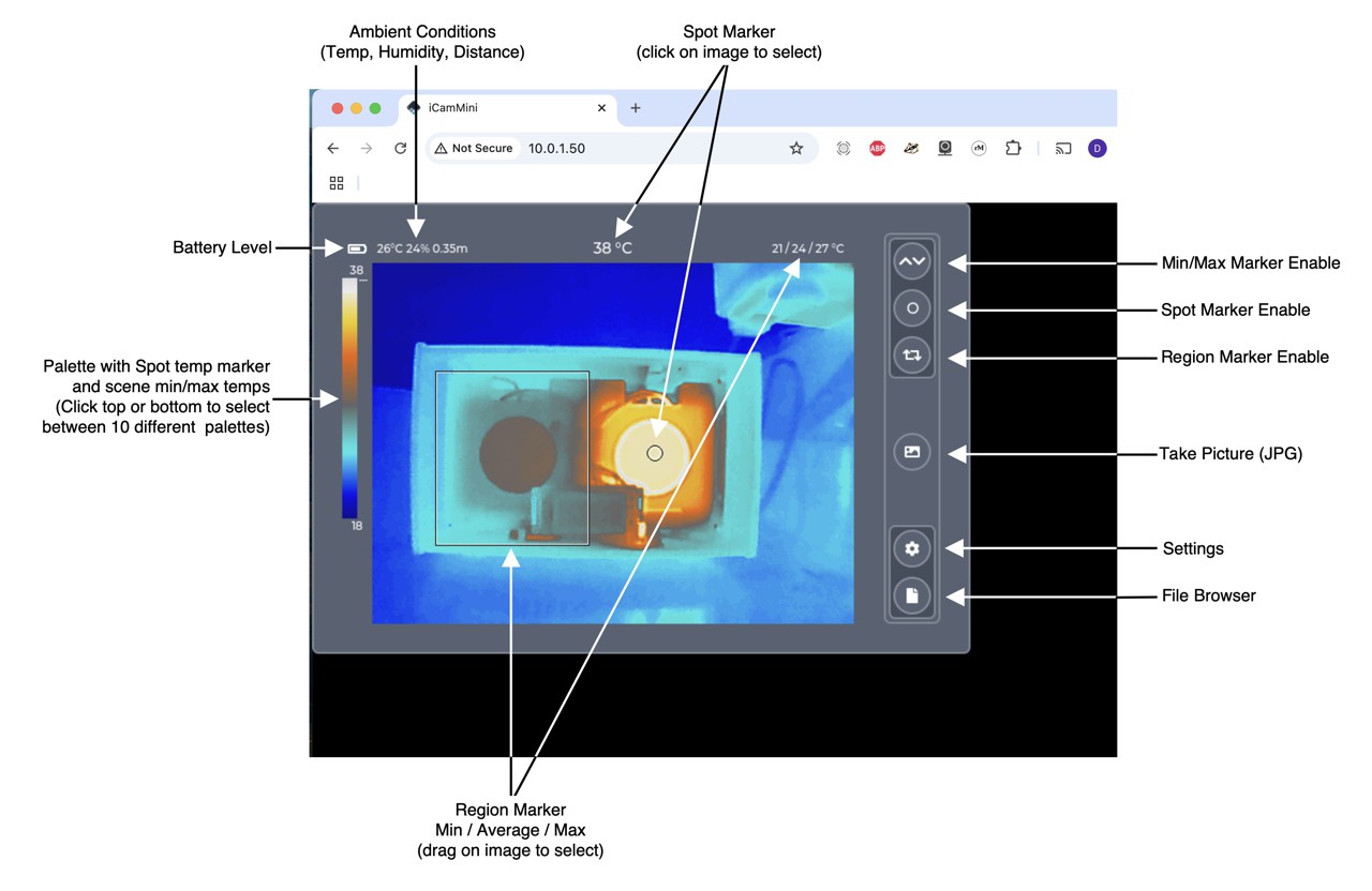
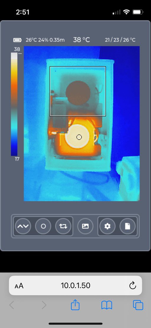
In Wi-Fi mode the camera runs a simple web server that can be connected to by a single desktop or mobile browser. The same LVGL GUI as iCam, but slightly resized based on the browser, is displayed through the magic of websockets and emscripten. It supports rotation for mobile devices.
Video Interface
The video interface is designed to drive a 75-ohm video device like a monitor or transmitter. In actuality the Rev 1 prototype can't quite achieve the 1v p-p required voltage range because I was overloading the DAC output so the Rev 2 includes a video amplifier.
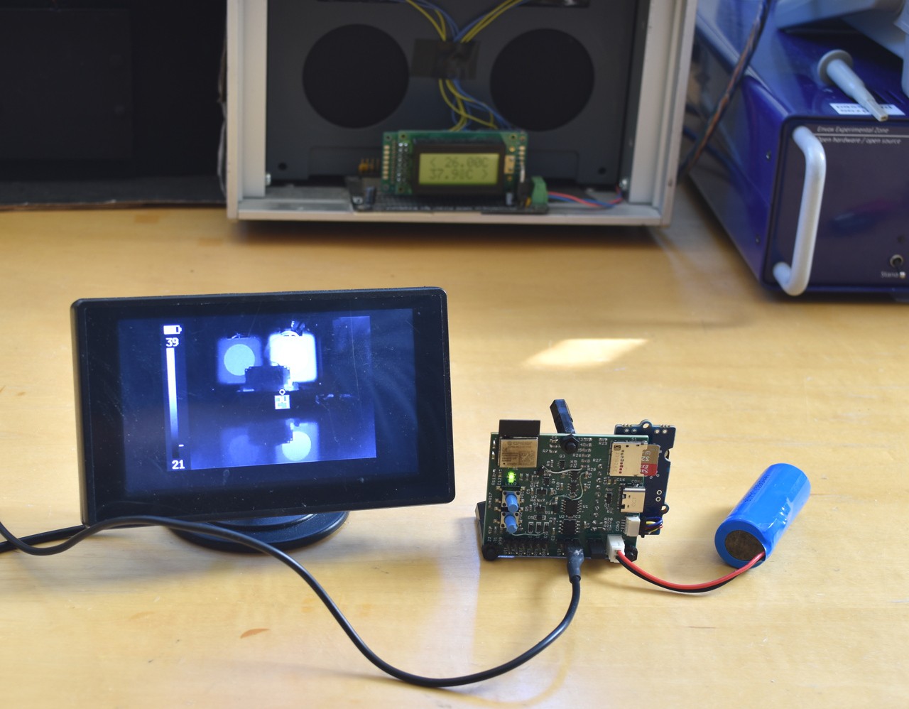
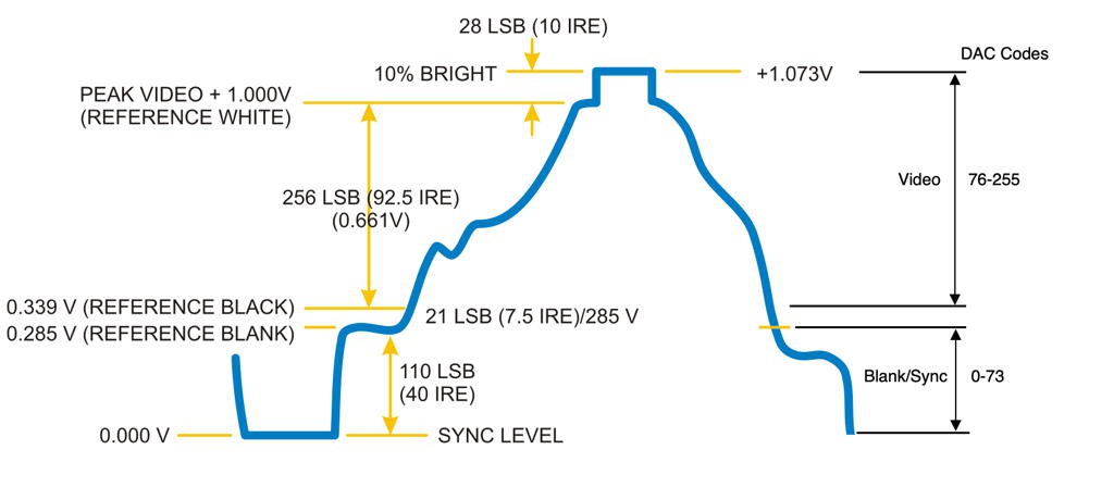
The video output is generated using the ESP32 8-bit DAC and DMA engines with heavily modified code that started out as aqauticus' ESP32 composite video library. The original code could only display 51 brightness levels. My code can display 170 brightness levels. The reason all 256 DAC output codes can't be used for video levels is that some of the signal has to be used for blanking and sync control as shown below.
The output can display a spot meter and temperature, the palette with min/max temperatures and min/max markers showing the hottest and coldest points in the image.
Since the output is monochrome-only I can only support two palettes: white-hot and black-hot. I looked at supporting color but the limited DAC range would essentially force the use of only one palette unless I was willing to significantly reduce the number of displayed colors at a time.
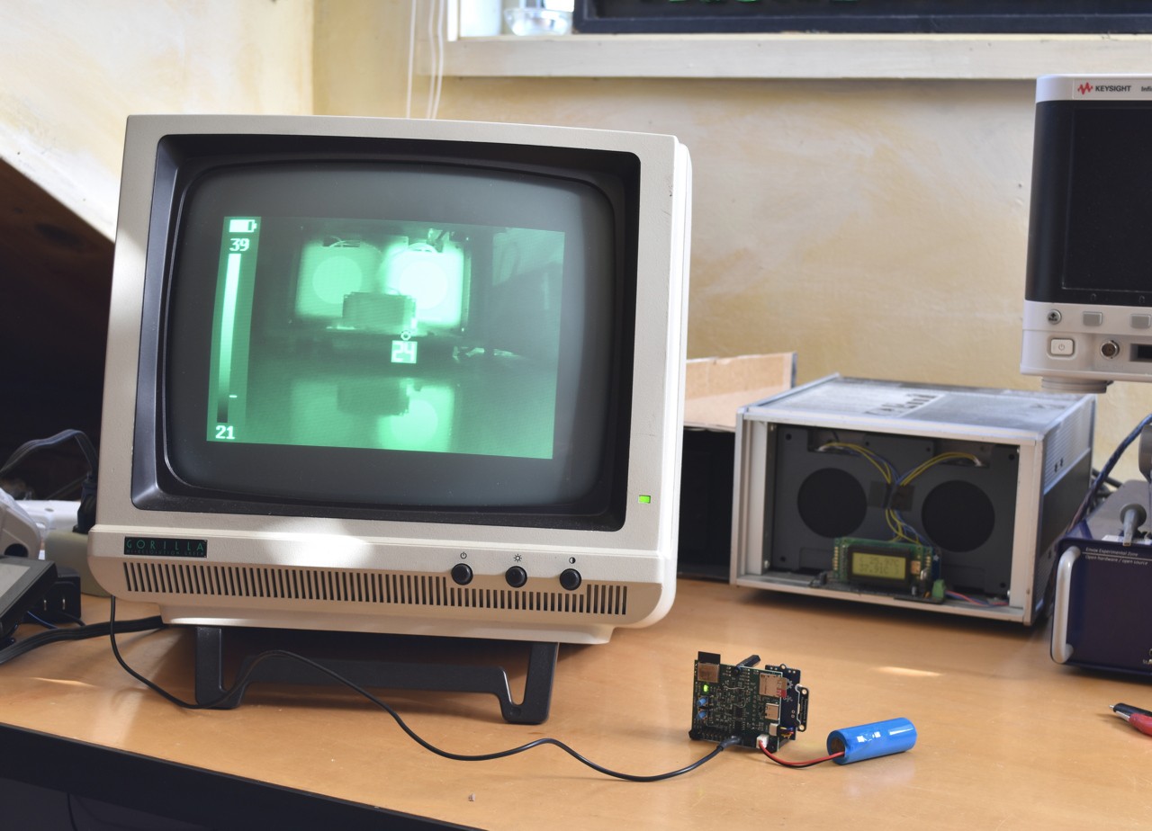
It was fun to connect it to an old CRT monitor and see it work- felt very old-school. This picture doesn't do it justice.
 Dan Julio
Discussions
Become a Hackaday.io Member
Create an account to leave a comment. Already have an account? Log In.
What a fabulous post this has been. Never seen this kind of useful post. I am grateful to you and expect more number of posts like these. Thank you very much. https://www.imedicarecard.com
Are you sure? yes | no