Close
0%
0%

M808B - Coilgun Tank

A tank controlled by bluetooth capable of shooting ferromagnetic projectiles

Similar projects worth following
This is a project for the technology class of the last year of high school. We are making a robot that can be controlled from an Android phone through bluetooth. The robot will be able to shoot ferromagnetic projectiles using a three-stage coilgun.

To do this project we divided the work in hardware and software. Antonio will do all the harware related stuff (designing the circuit, testing the coilgun, ...) and I'll write all the software (both the microcontroller and Android app), design the 3D model of the cannon and the tank itself and mount it.

Currently, the tank's movement and turret orientation can be controlled from an Android app that emulates a videogame joystick. The circuit and the tank body is finished, but we still have to 3d print the canon.

This is the list of things that we have to do:

  • Program the code for the canon
  • Add a LED lighting system - almost done
  • Design a reloading system for the cannon's shells. - done? (we have to see)

  • 1 × Tank Chassis
  • 1 × 12v Sealed Acid Battery 2.2Ah
  • 3 × 0.8mm 100g enammeled copper wire
  • 1 × ATMEGA328P in TQFP Microprocessors, Microcontrollers, DSPs / ARM, RISC-Based Microcontrollers
  • 3 × CNY70 Sensors / Angle, Position

View all 31 components

  • Update on the project

    Ramón Calvo10/01/2017 at 19:55 0 comments

    It has been a while since we posted anything here, but we haven't abandoned the project. In fact, it is going pretty well, and if everything goes as expected, the tank could be finished by the next week (and submit it for Anything goes).

    First, I got a 3D printer, a Creality CR-10 from Banggood. The printer is outstanding and the quality of the prints is amazing. I had absolutely no idea about 3D printing and I got it working and printing the same day it arrived.

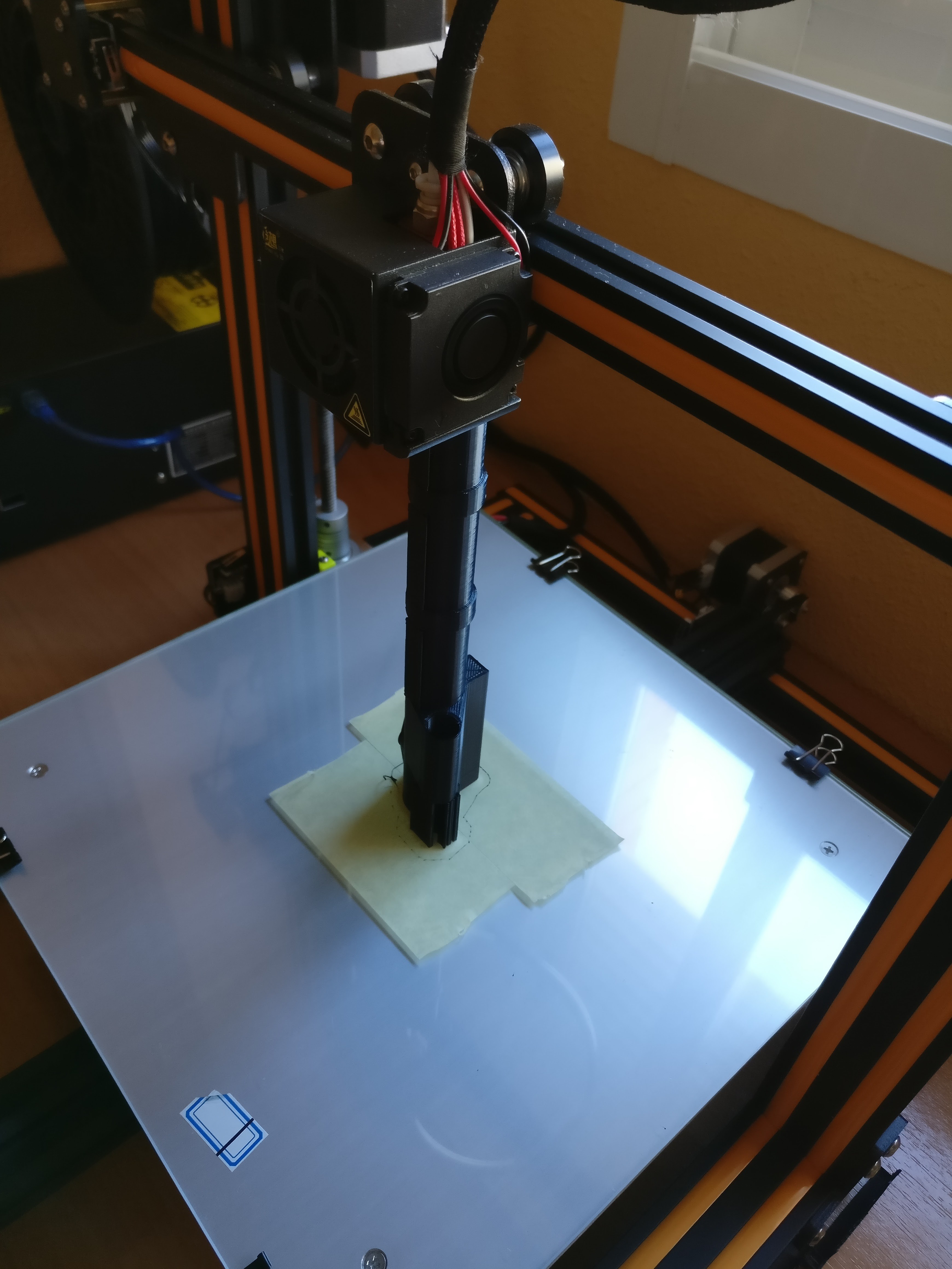
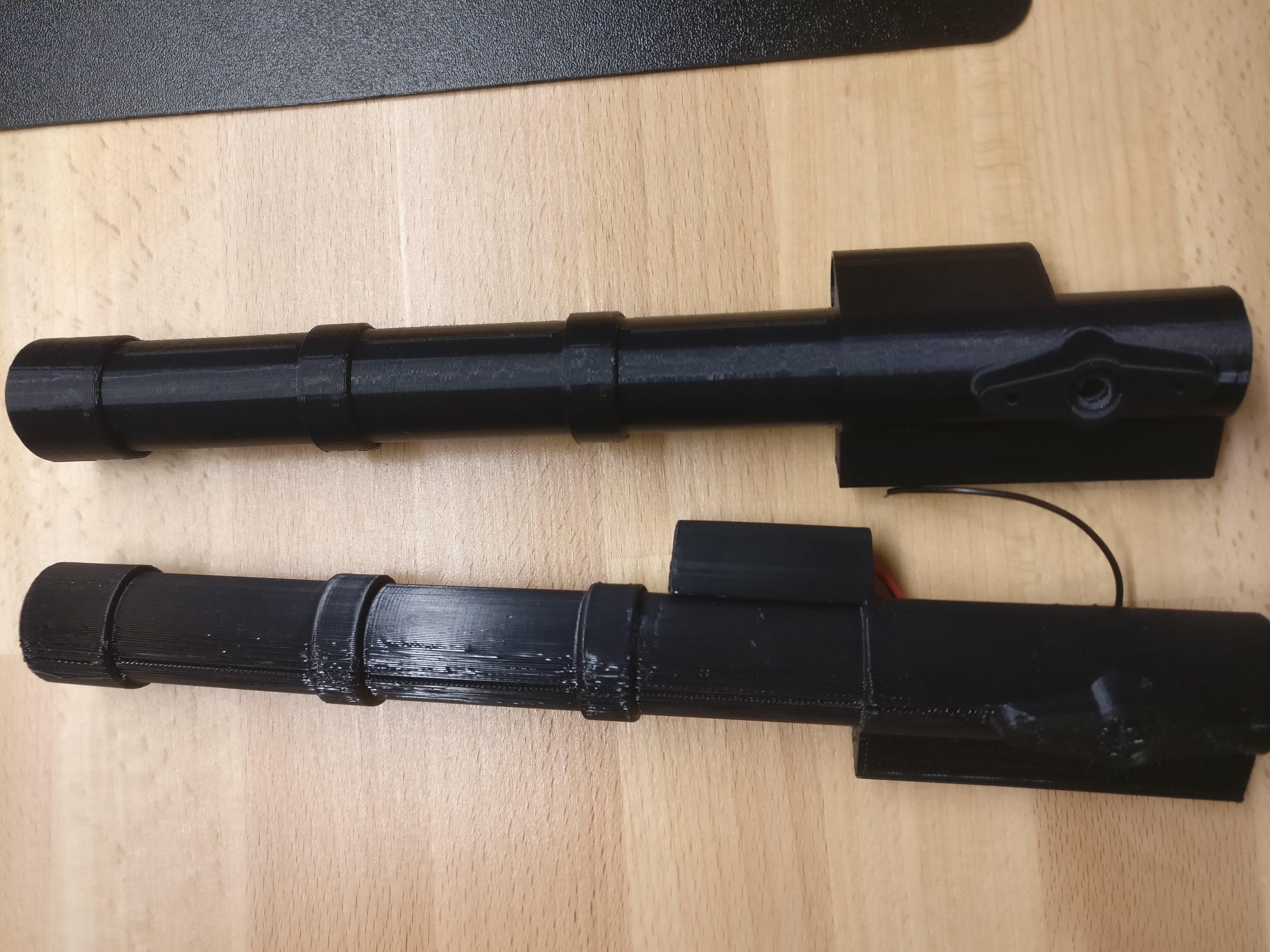
    After a few days of training, I tried to print the tank's cannon. I printed it laying on the bed thinking that the direction of the layers would make the piece stronger, but it wasn't such a good idea. A lot of supports were needed, the interior of the cannon wasn't perfectly round and the support between the laser enclosure and the cannon itself was difficult to remove (there is still a bit of plastic that impede the coil to be in its position.

    So  I modified a bit the cannon and printed it. This time vertically. The result was good and it seems to be strong despite the direction of the layers is parallel to the direction of the forces that will act on it. I also used 40% infill which helped a lot.

    A comparison of both cannons. No need to say which is which.

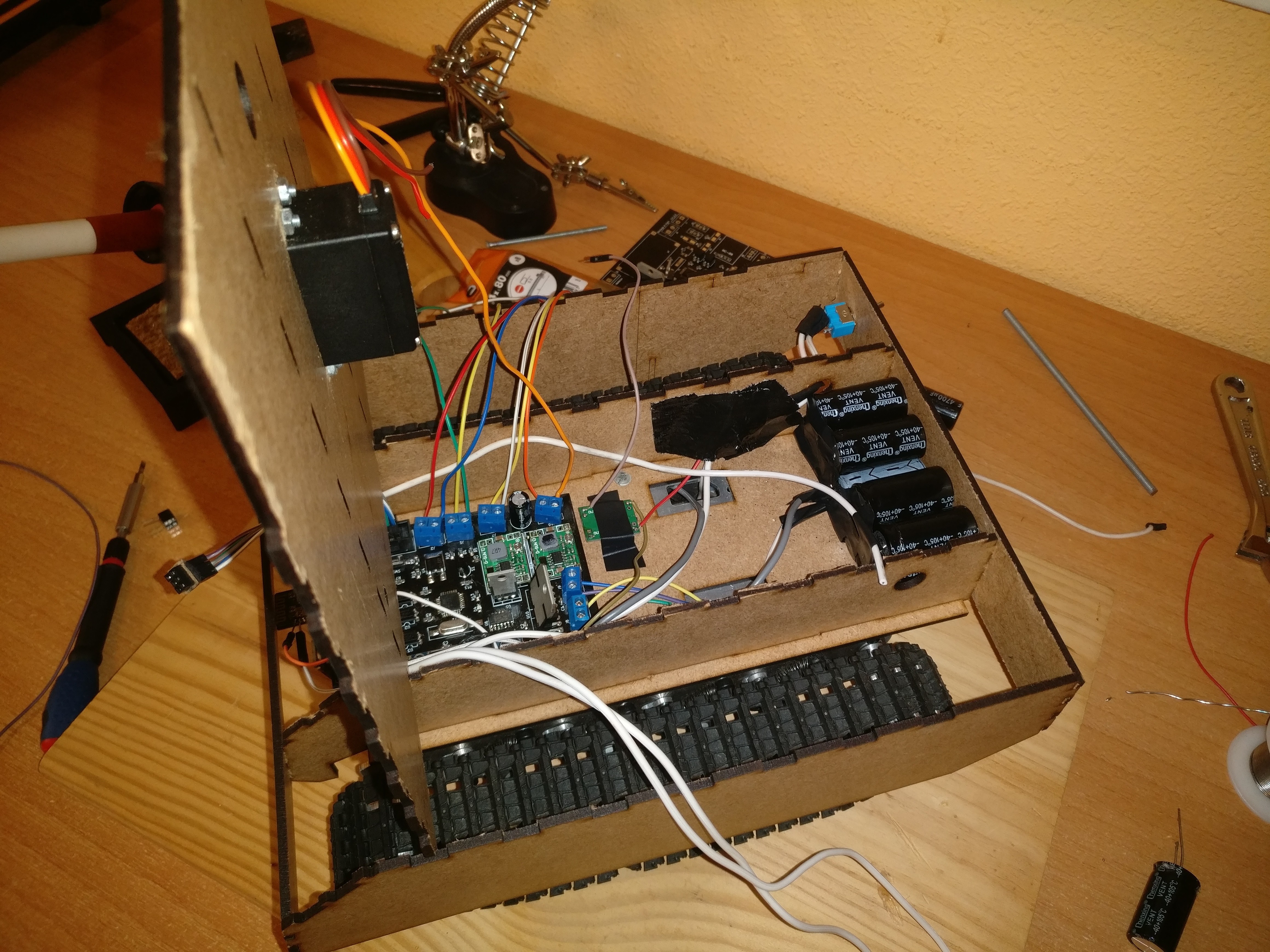
    Also, changes have been made to the tank. It's 'armor' has got 2 cm higher and it has gained more space at the back. This allows for a better layout of the electronics and the capacitors are now hidden inside the tank. I also modified the other existing parts so now they snap to each other with no need for glue.

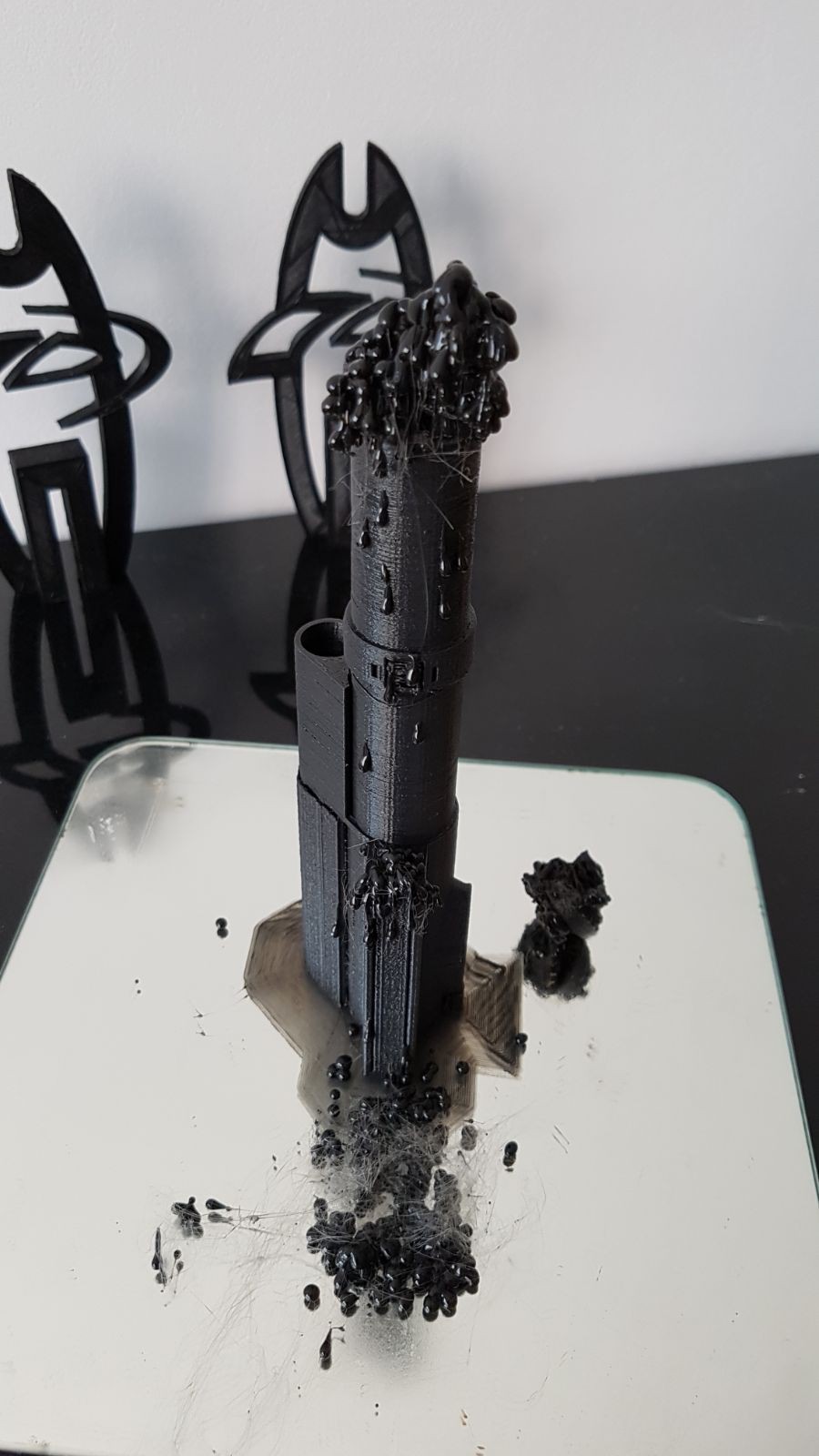
  • Problems with the 3D printer

    Ramón Calvo07/22/2017 at 09:13 1 comment

    Unfortunately, we can't finish the project for the Wheel, Wings and Walkers contest. The local hackerspace and some friends' 3D printers didn't have the expected results. Anyways, we will finish the project as soon as I can print the canon (a 3D printer is coming from china :) )

  • The chassis is mounted

    Ramón Calvo07/16/2017 at 21:46 0 comments

  • The tank is cut

    Ramón Calvo07/14/2017 at 07:05 0 comments

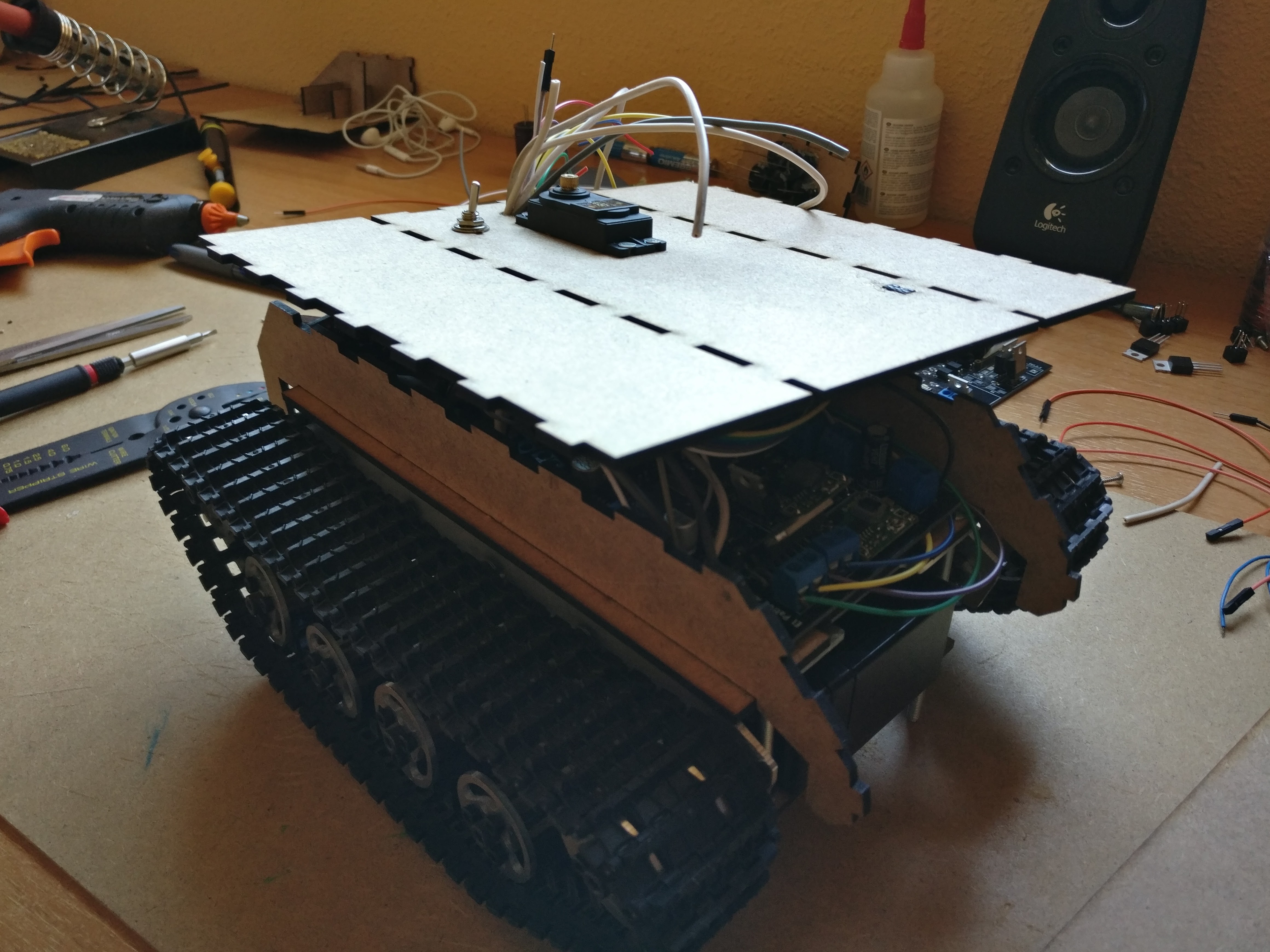
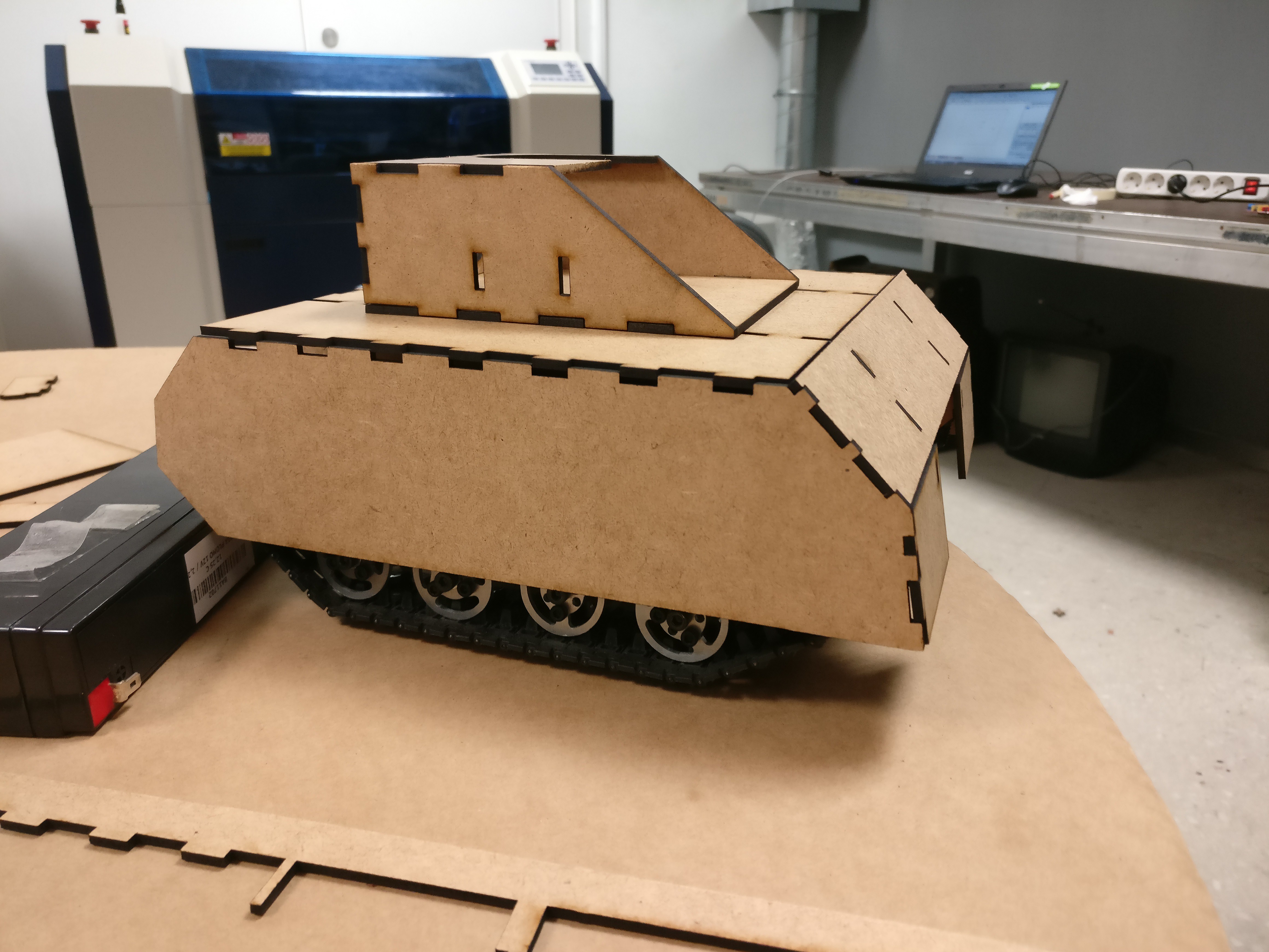
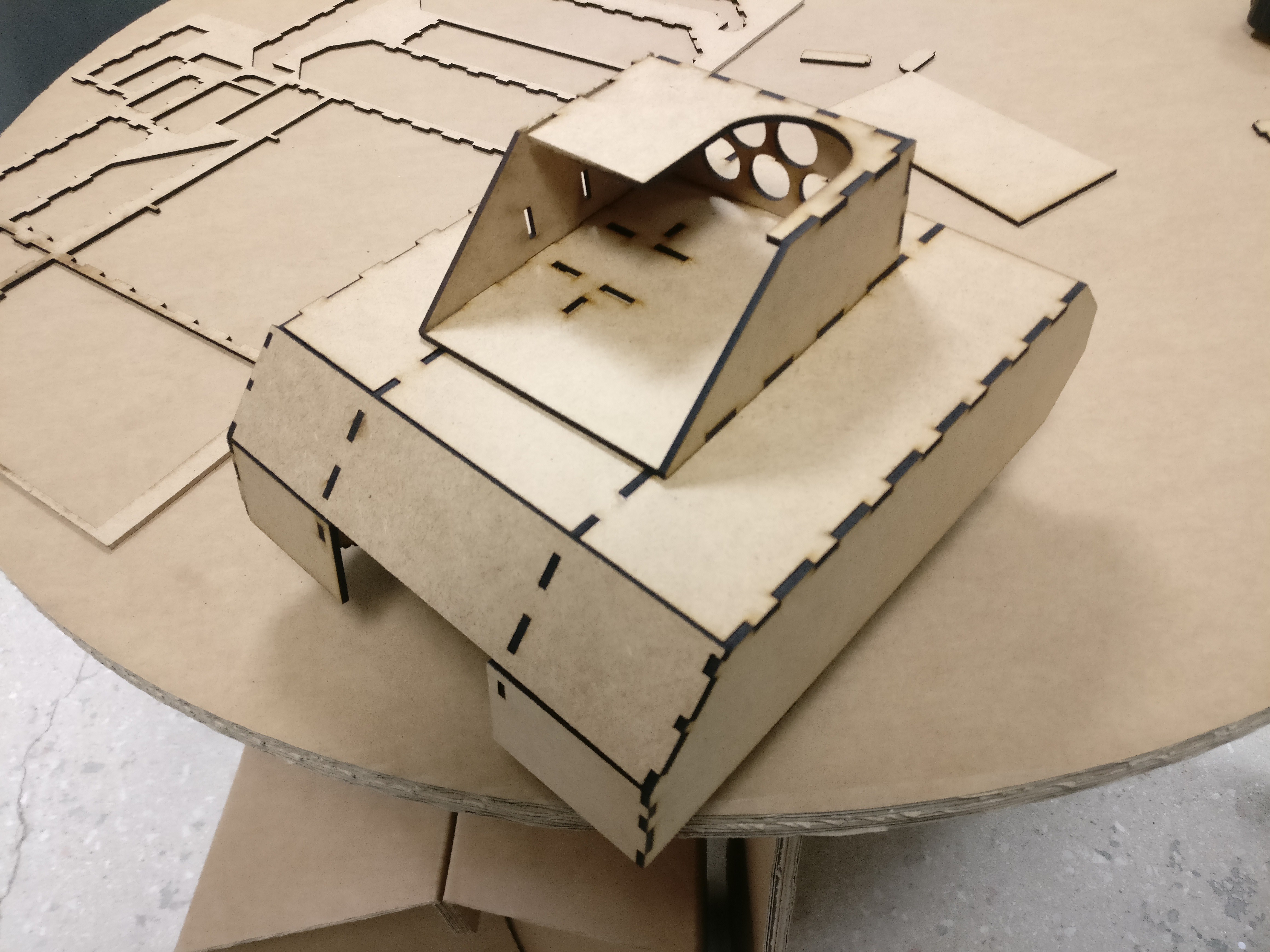
    Here are some pictures of the tank. The pieces fit perfectly. It is not glued yet and it stands for itself.

  • Final touches to the model

    Ramón Calvo07/09/2017 at 21:37 0 comments

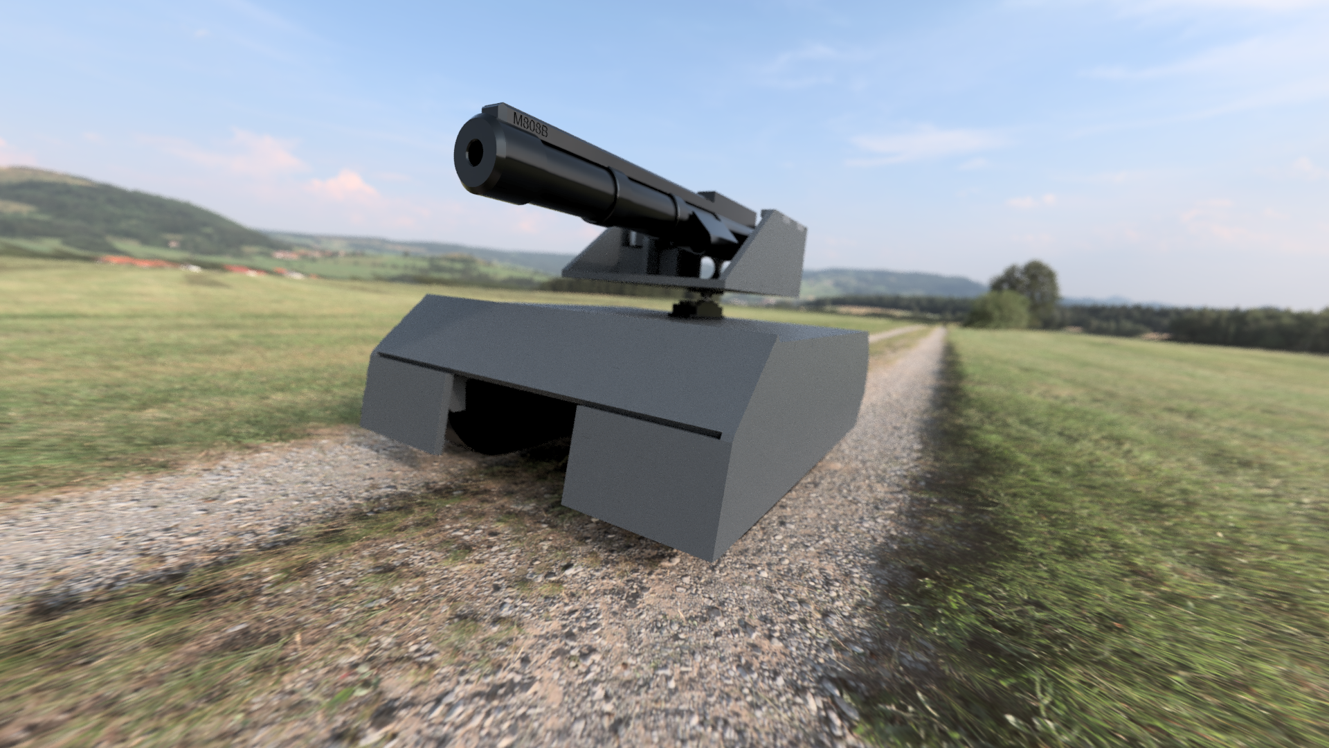
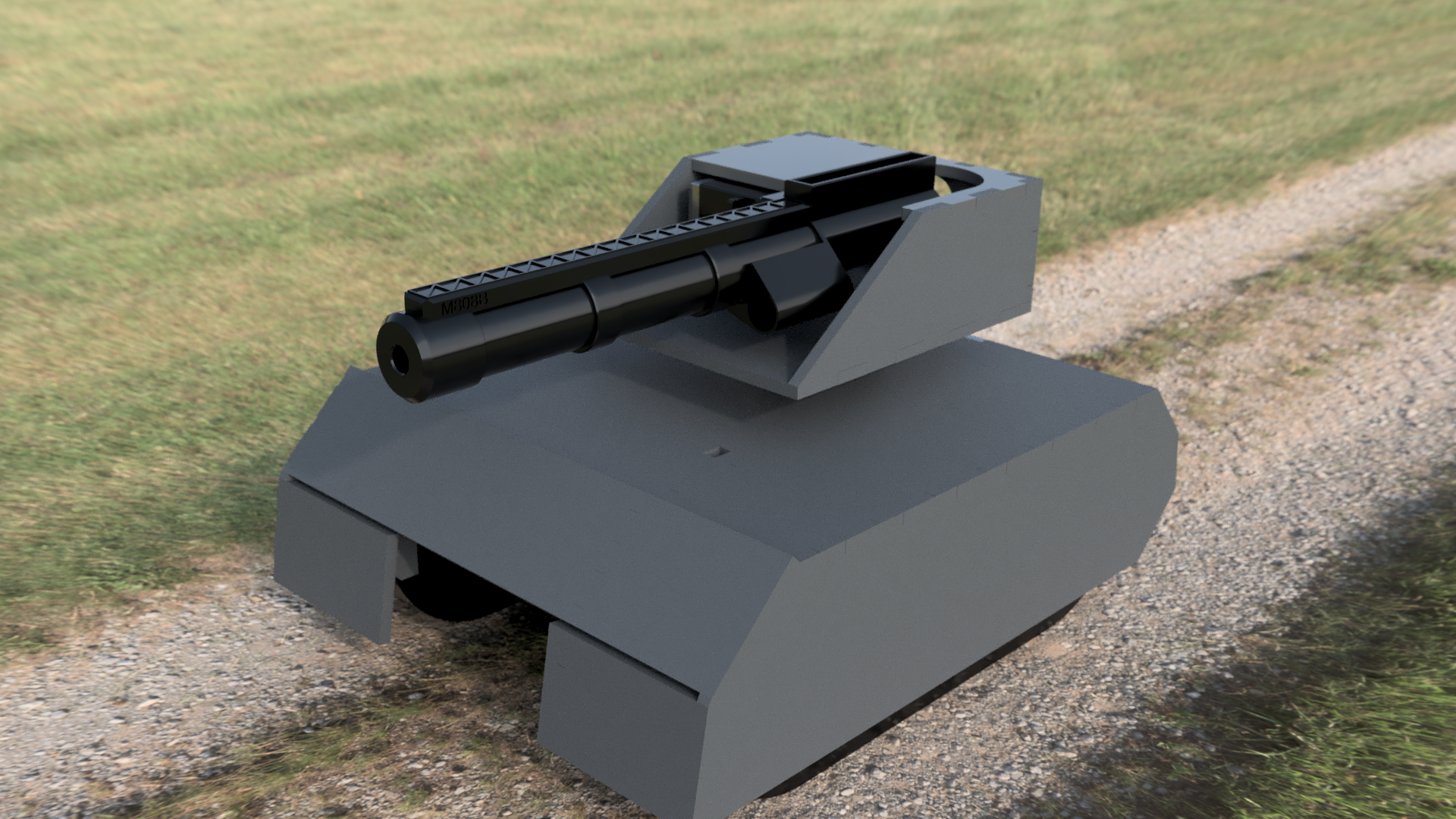
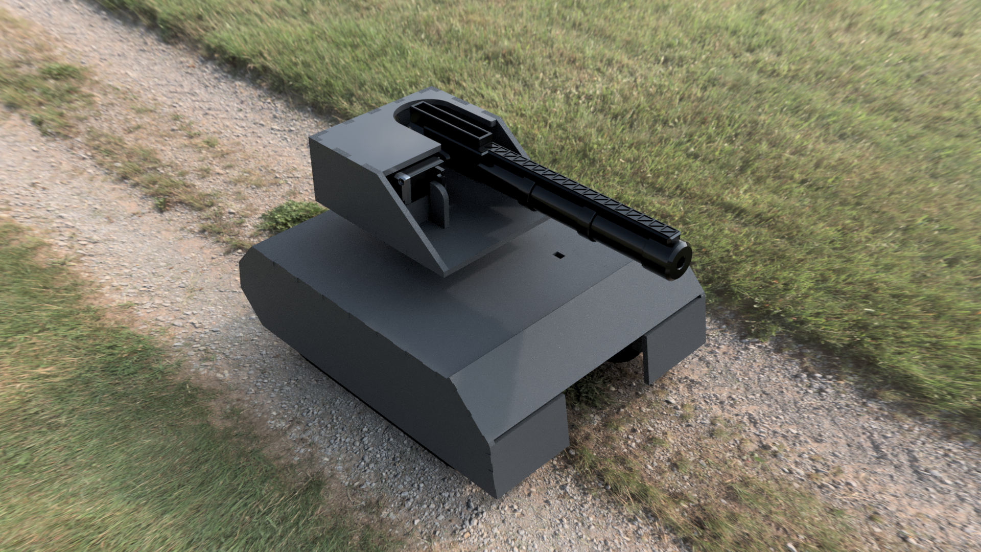
    After a long session of working on the model, I have finally finished it. This is my first project using Fusion 360 so I may have made some mistakes and the model quality could not be perfect but I am happy with it.

    I also made the connections between pieces 0.2 mm smaller on every side. That's because the laser cutter erases from 0.1 to 0.2 mm and that way I can stick the pieces together without any glue.

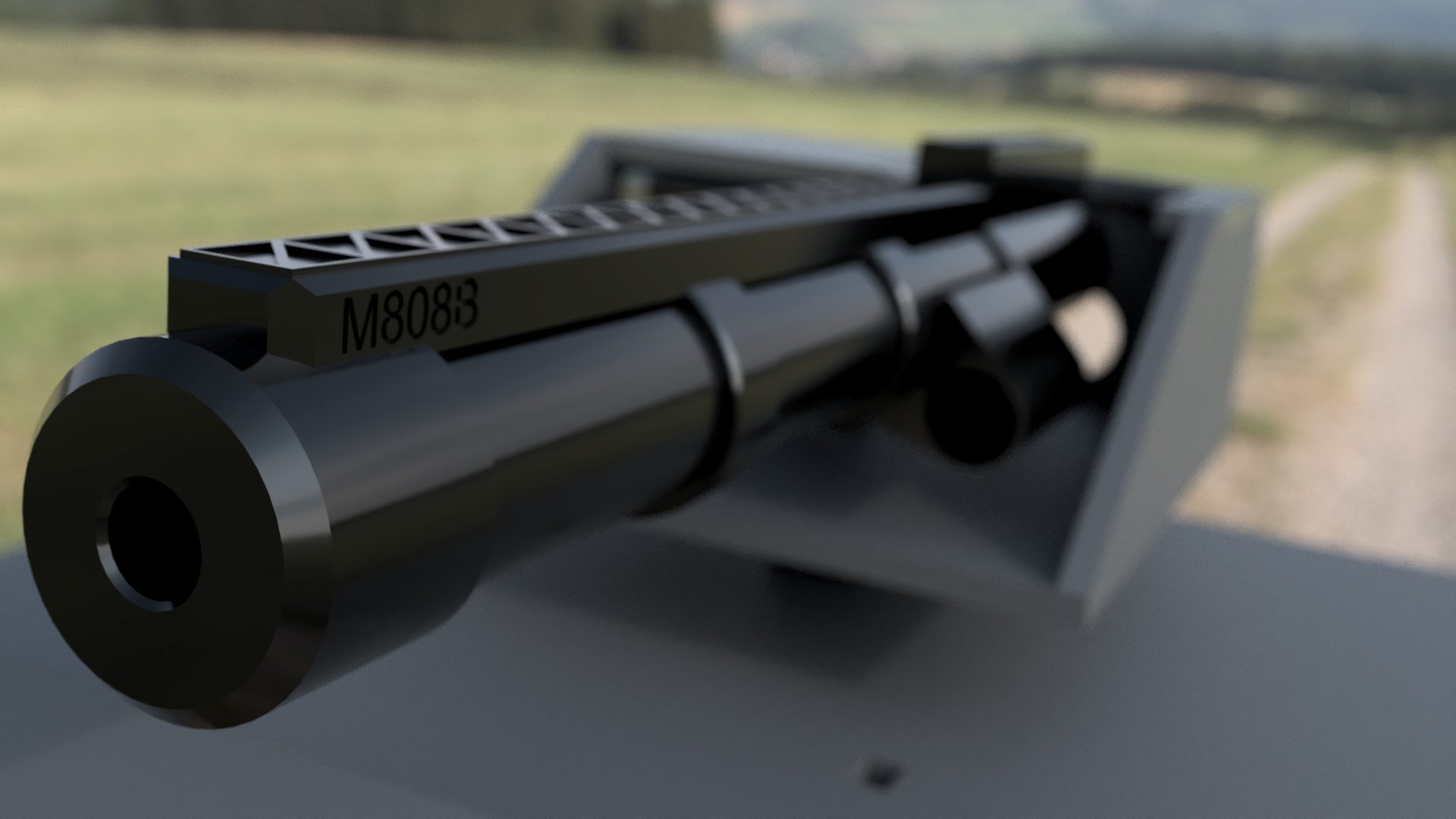
    Here are some renders of the tank:

  • We have not given up

    Ramón Calvo07/05/2017 at 17:30 0 comments

    Although we haven't updated the project for a while (almost three months!), we had not stopped working on this project, but it is true that we slowed down because we had to do our final and university entrance exams. So I will make a quick update of what has been happening those months.

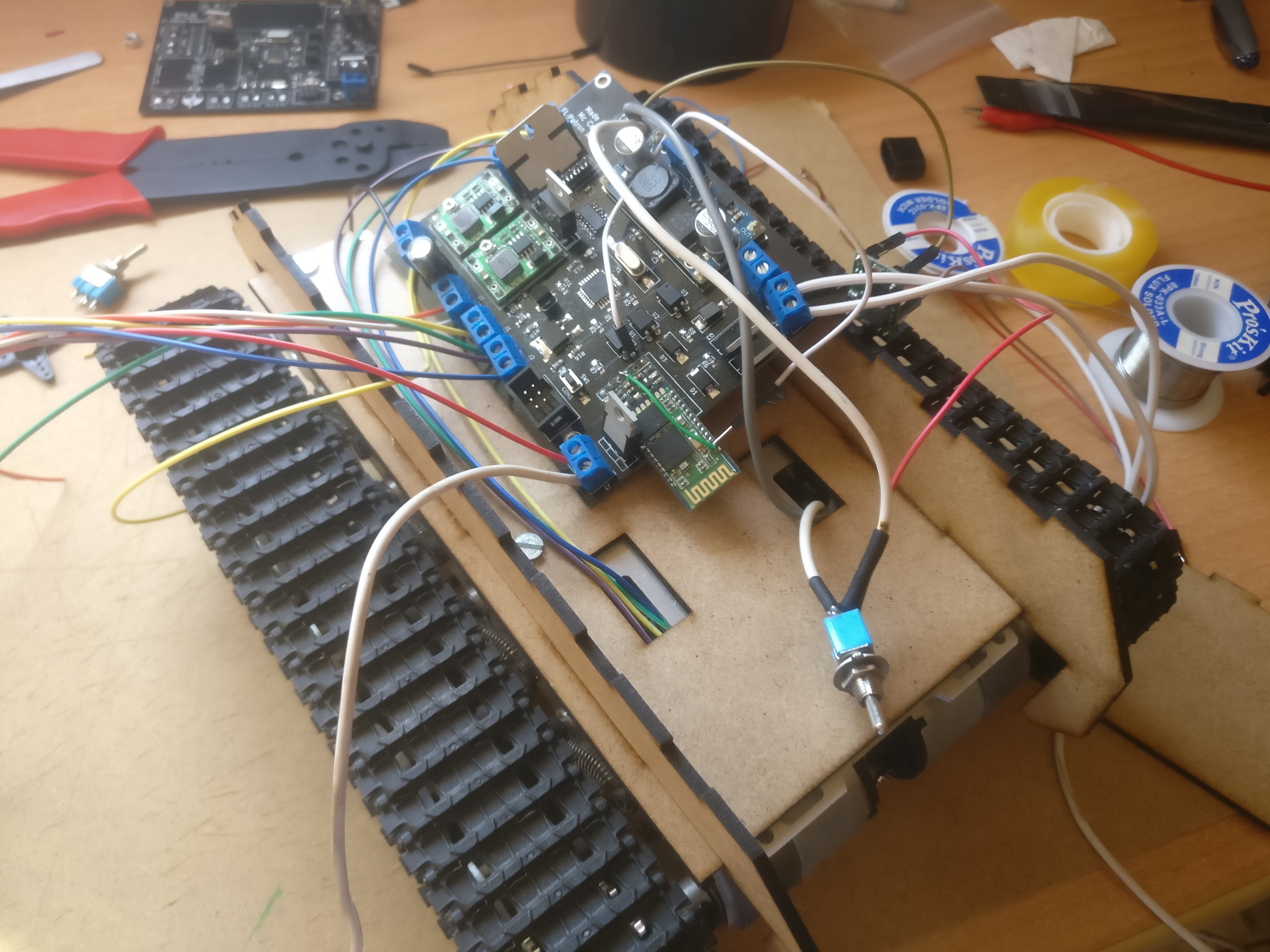
    We soldered the components and tested that everything worked fine, but when I started programming, I noticed that the motors and servos weren't connected to the pins I expected (timer0 of the AVR [OCRA and OCRB] to the dc motors and timer1 to both servos). The servos were connected to timer0 and the left and right dc motors were connected to a different timer. That was my mistake. Before sending the PCBs to Elecrow I didn't check that I sent Antonio the wrong schematic.

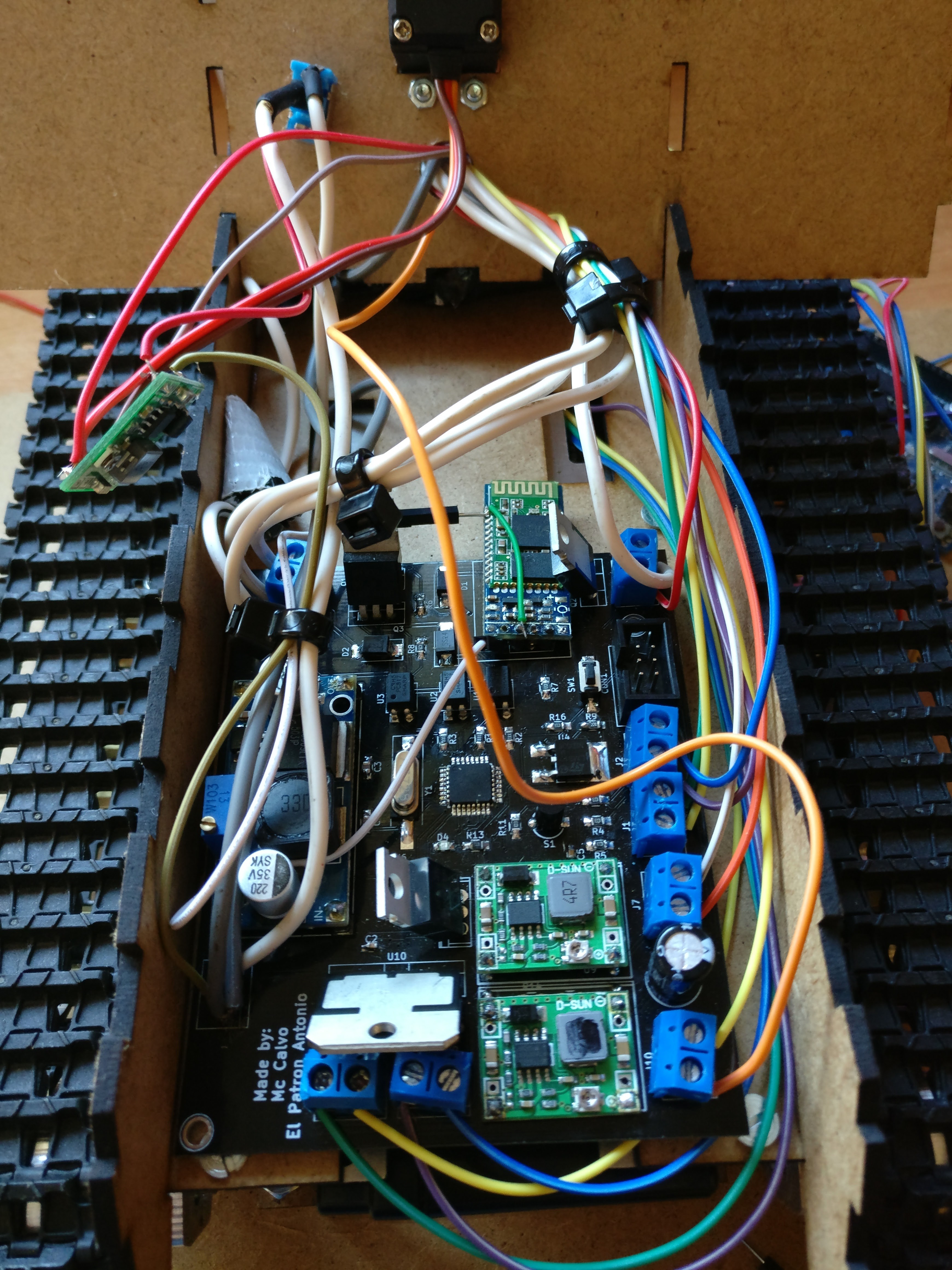
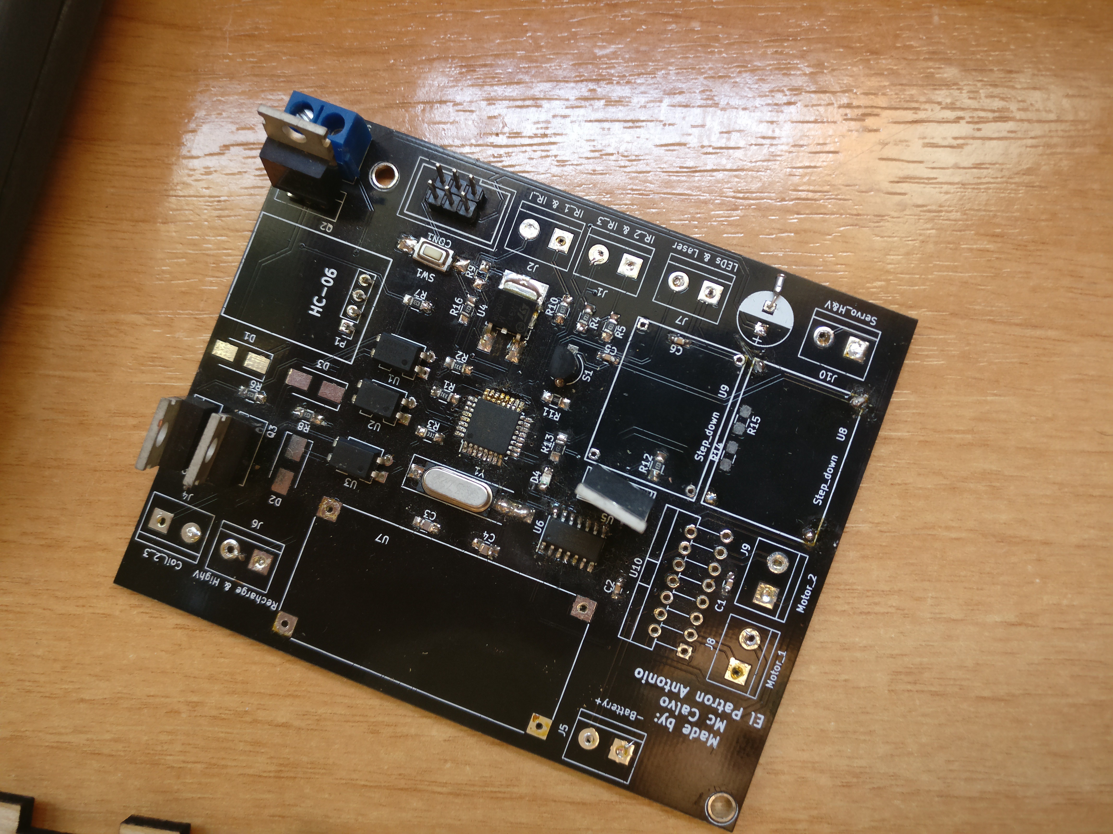
    The first board, depopulated after we realized of my mistake

    So we changed the PCB design and we had them made by Elecrow, again. This time they were offering the same service for half the price, so we got the PCBs made and shipped to Spain for less than 10€. We soldered everything, re-using the electronics of the previous boards. The bluetooth breakout board lost a pad during the process so I did a work-around soldering the Rx pin directly with a white wire.

    Once everything was ready, I wrote the new code for the well-connected motors and the servos. Finally, everything worked just fine. Here is a video of the whole thing:

    I have to say that the left joystick works fine (although it needs some adjustments) but I swiped it gently so the tank wouldn't fall off the table.

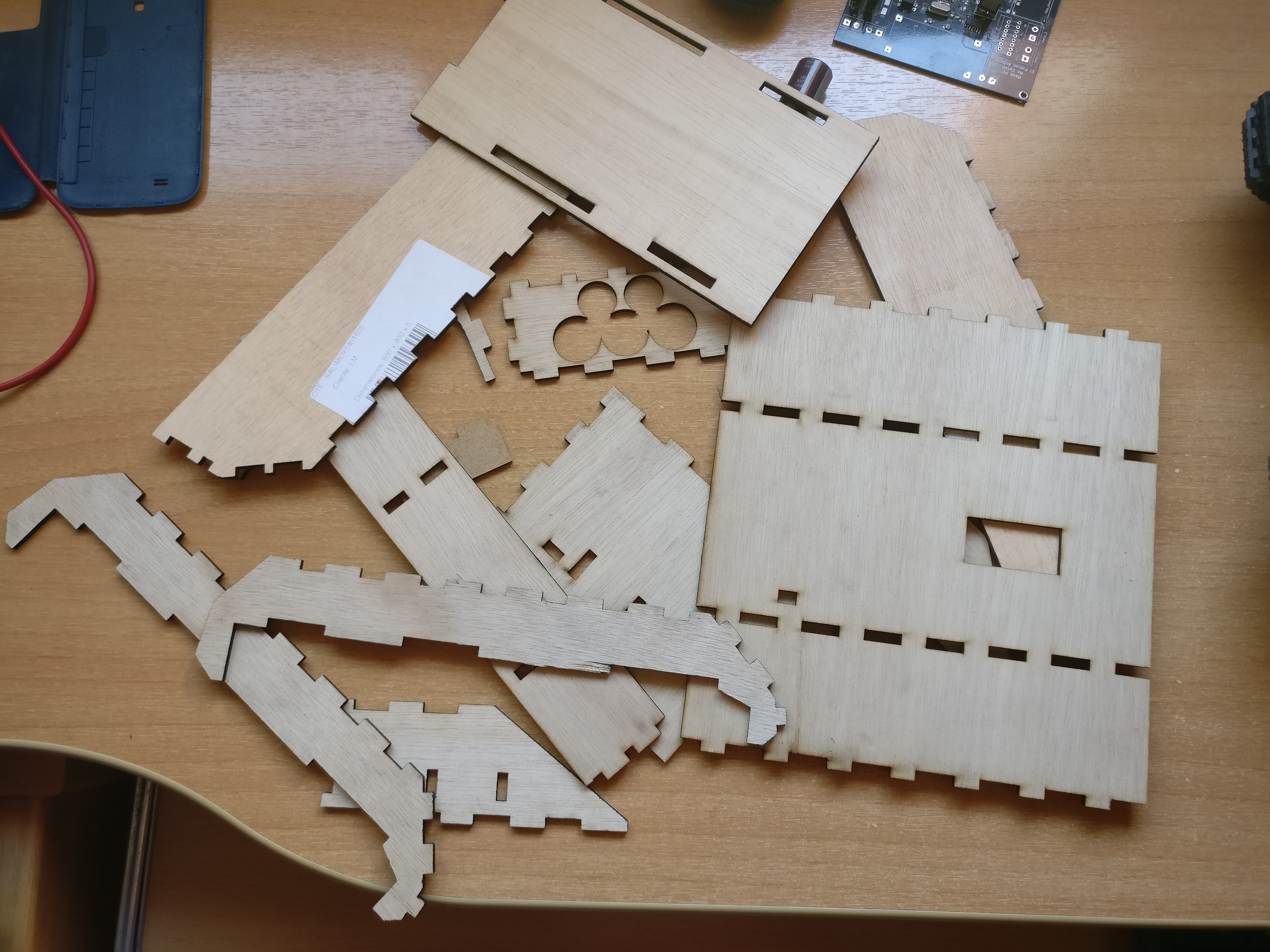
    Also, I have used the laser cutter to cut the tank model. But the wooden boards weren't of the width we needed (3mm instead of 4mm), so I use what I have only for prototyping.

    Here is a picture of all the pieces:

    We still have to make the coil canon, let's see how lucky we are...

  • PCBs have just arrived!

    Antonio Aslan04/14/2017 at 15:02 0 comments

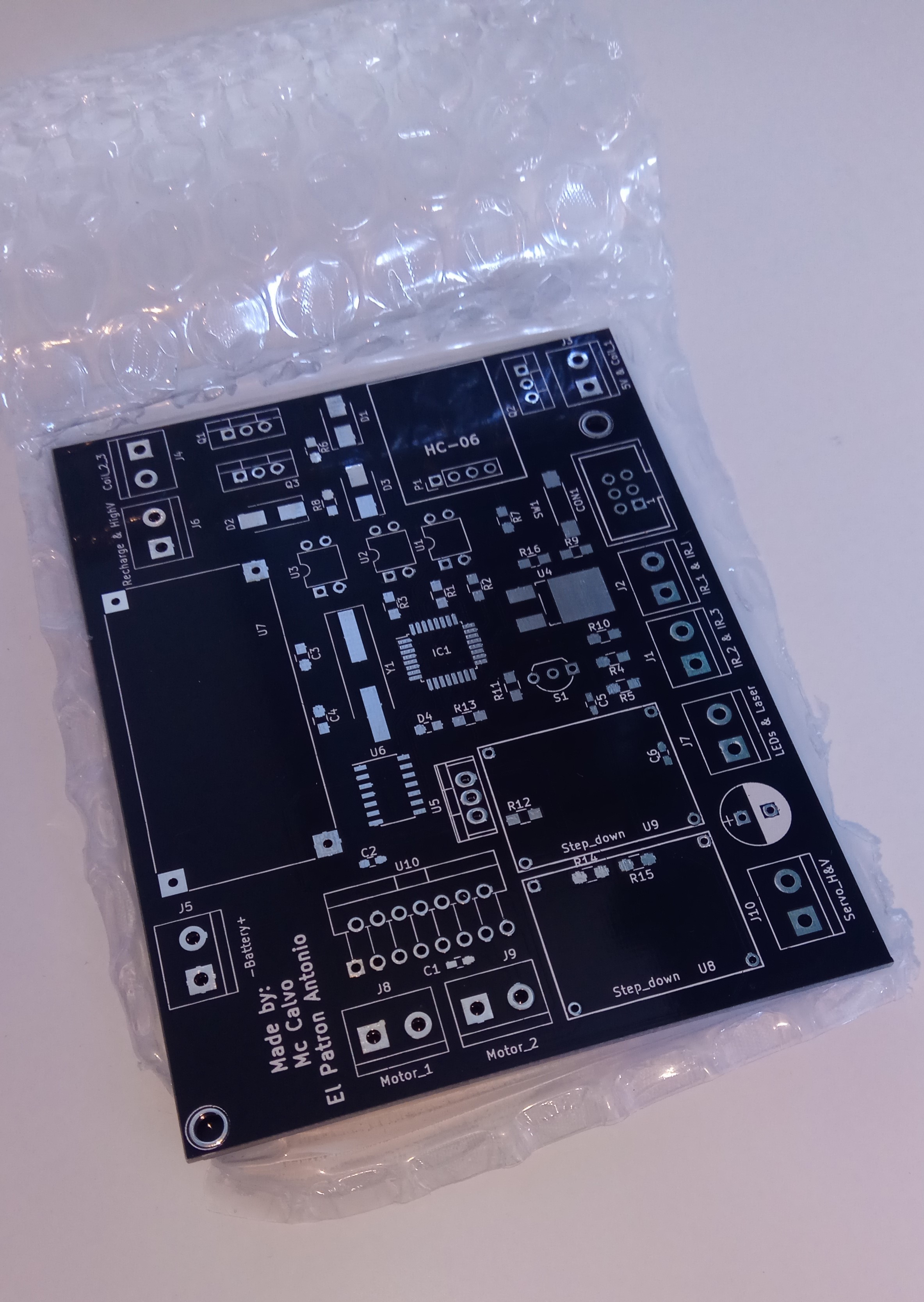
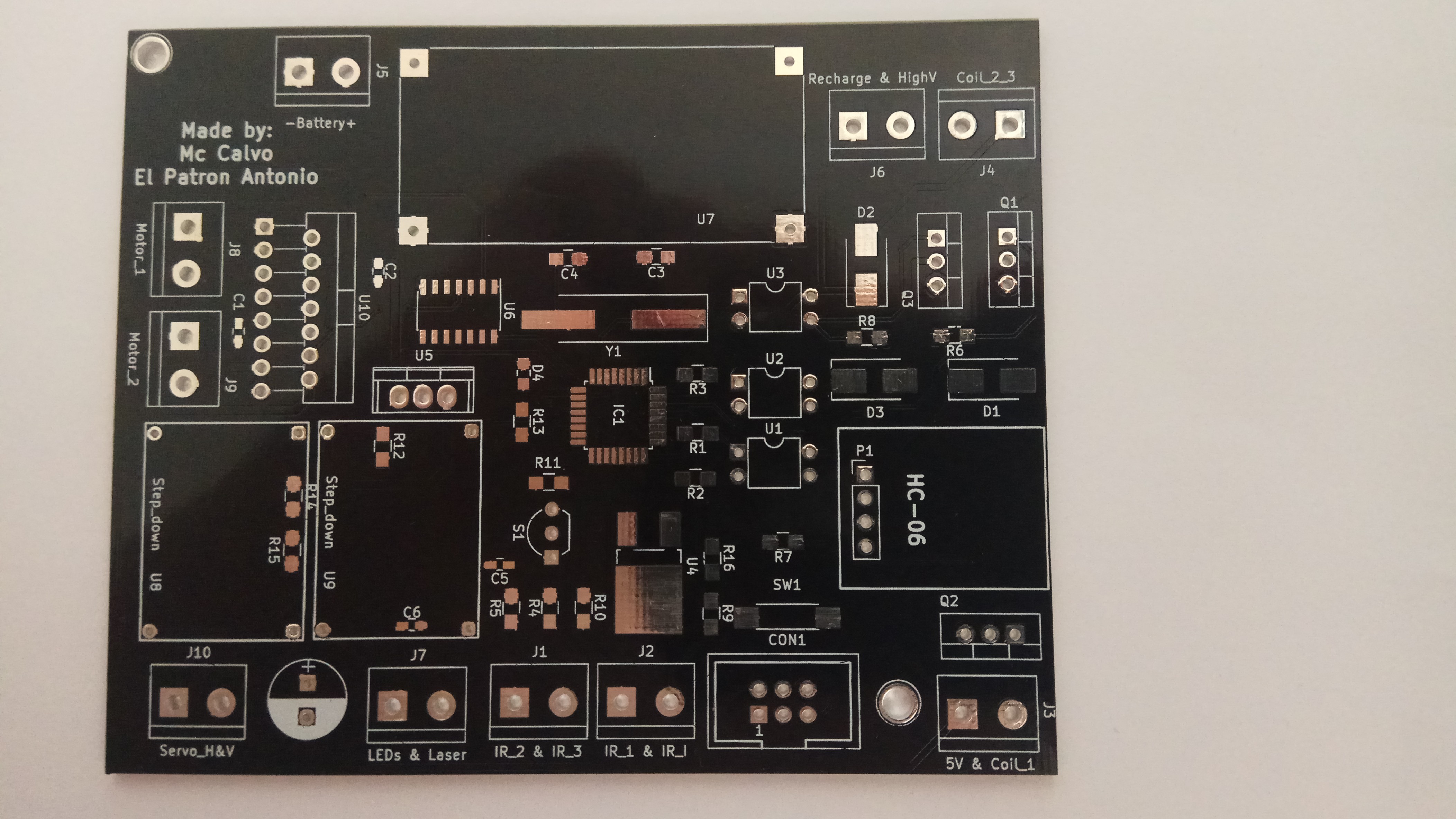
    Luckily, everything went perfect during the prototyping stage: No MOSFETS died, the microcontroller didn't turn off when the gun was firing, and the motor driver worked fine. So after drawing the circuit and designing the PCB in KiCad we decided to send the board's Gerber files to a professional fabrication house. And after doing some research and comparing suppliers, we agreed that Elecrow was our best option. After a couple of weeks here they are.

    I ordered 5 of them because it was the minimun number and those cost about 16$ ( manufacturing + shipping). Also I thought that the package was going to arrive in a month ( that's the average time for shipping from China), but it only took 15 days for the PCBs to arrive. And I also have to say that the quality and overall look of the PCBs is awesome.

    So now we only have to wait for the rest of SMD components to arrive from China (they're probably arriving next week), solder the components and test the coilgun and the tank. And if everyting goes according to plan, the project will be finished in a month, but it may take a little bit longer because we're very busy with our final High School exams.

    PS: we're not releasing the PCB and other project related files yet because first we want to make sure that the project is working without any problems, and when it does, we'll upload all the files and building instruccions.

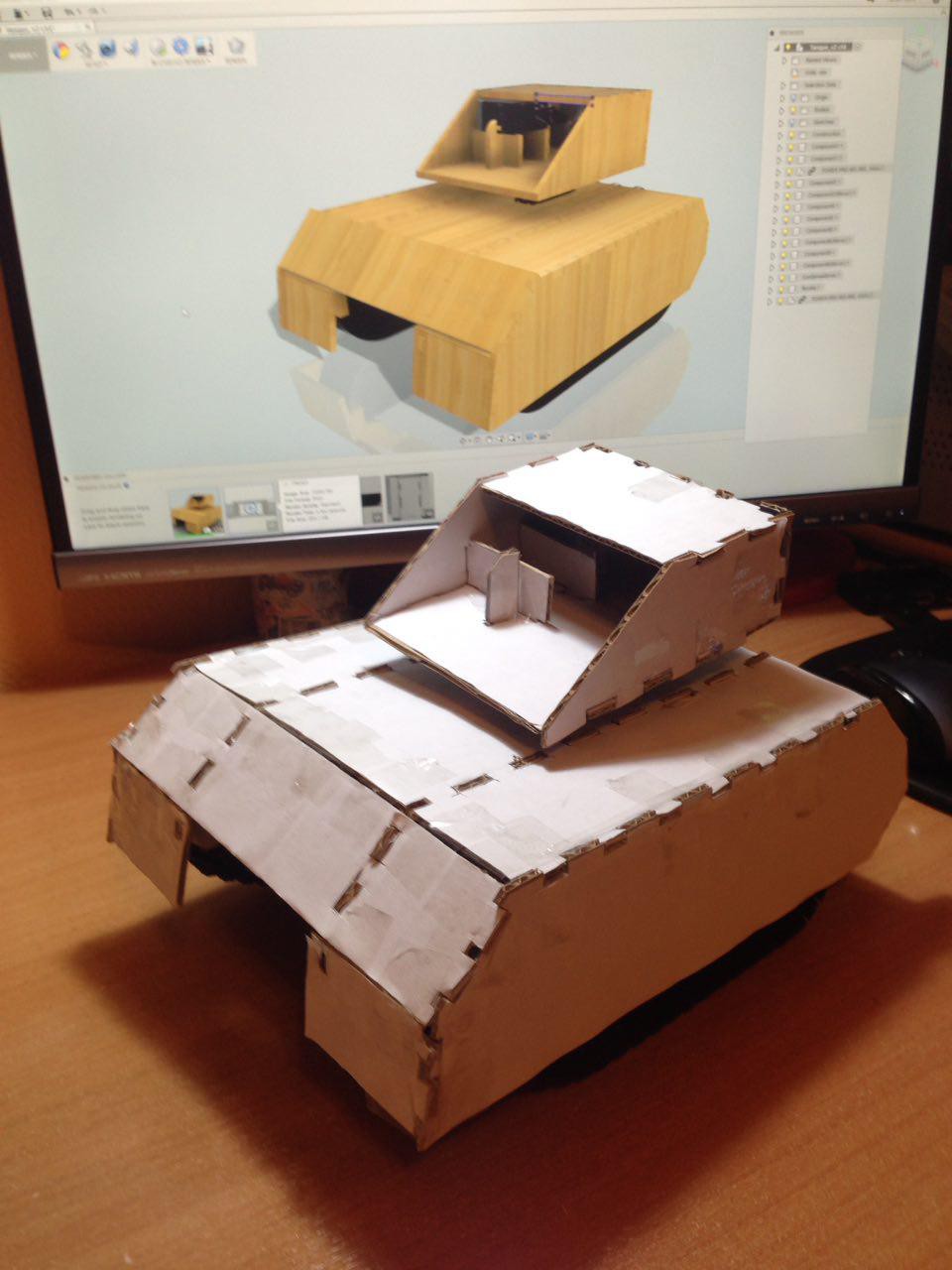
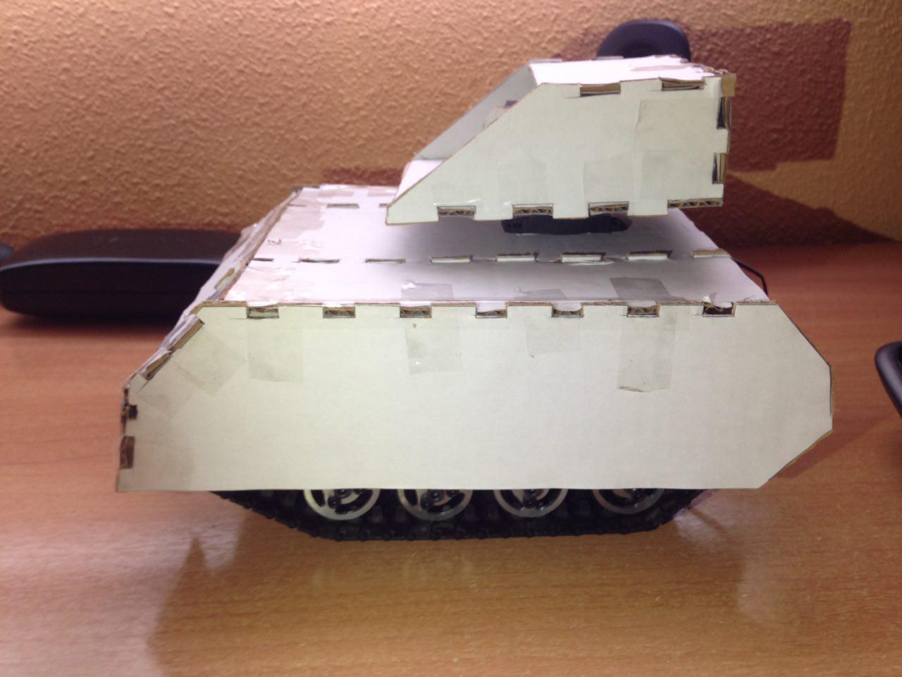
  • Cardboard prototype

    Ramón Calvo03/12/2017 at 13:27 0 comments

    Before building the wooden structure, I decided to build a carboard prototype first. This way we ensure the design has the dimensions that we want and the inner space required for the circuit.

    Thanks to this I realised it was a good idea to make the basis a few milimeters wider. Everything else fits perfect.

    The software used to make the 3D model is Fusion 360 (student version). It is the first time I've touched a parametric modeling tool and it os fantastic. At first, I considered learning FreeCAD instead, but after reading some forums, I found out that FreeCAD is not as competent as its paid counterparts, has some bugs and it's not easy to use. I had previous experience with Blender (great software) but it's not a great idea to use it for design (or so I've read).

    This is also the first prototype I've made with cardboard and I have to say it is a great material for quick testing. It is virtually free, has a decent strength and it is easy to cut with a cutter, which makes it perfect to work with.

  • Hardware: Done and To do List.

    Antonio Aslan02/26/2017 at 21:15 0 comments

    On the hardware side, there is plenty of work to do. Currently, I have done the circuits for most of the parts of the project, for example the circuit for every coil stage, lights and laser pointer is done, and now I have to put it all in a circuit with the microcontroller and Bluetooth circuitry. But before that, some final testing and prototyping have to be done on the coilgun circuit to ensure that no more MOSFETs are going to get fried.

    If everything goes well in prototyping, making the complete circuit will be an easy task. Then I need to make the PCB, we are thinking between making it ourselves at home with HCl or to send it to a fabrication house like Elecrow. Once I have the PCB, some more testing will need to be done with the circuit and the 3D printed turrent before we put it on top of the tank. And that is going to be the last step, mount the turrent on top of the tank chassis and test it.

    In the future and if everything goes OK to that point, I plan to add a reloading system to make the tank completely autonomous. But first we need to see how the project evolves.

  • Hardware: Gun's Firing Mechanism.

    Antonio Aslan02/26/2017 at 20:29 0 comments

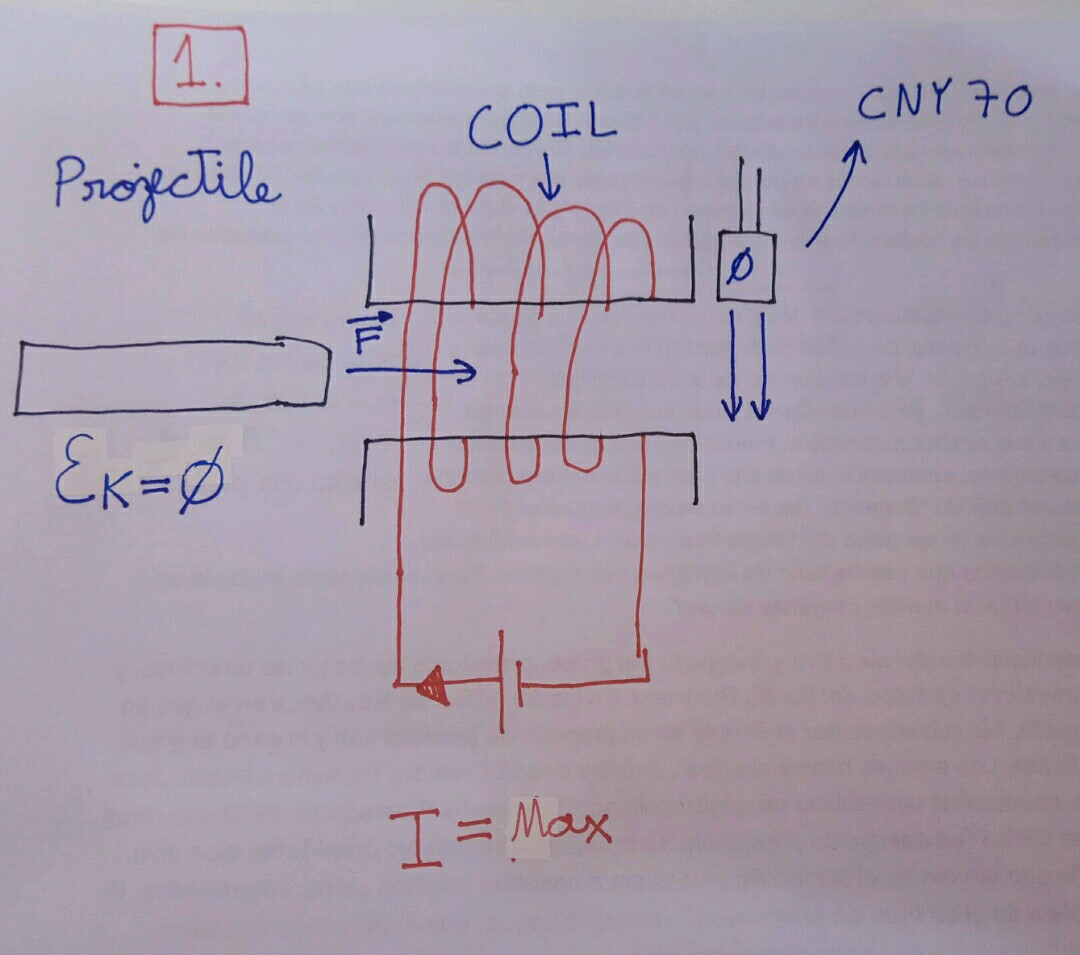
    The cannon has three coil stages that accelerate the projectile one after the other. First, the coil is off and the projectile isn't moving. But then we turn on the coil, current starts to flow through the coil and the bullet starts to move because the magnetic field of the coil is accelerating it.

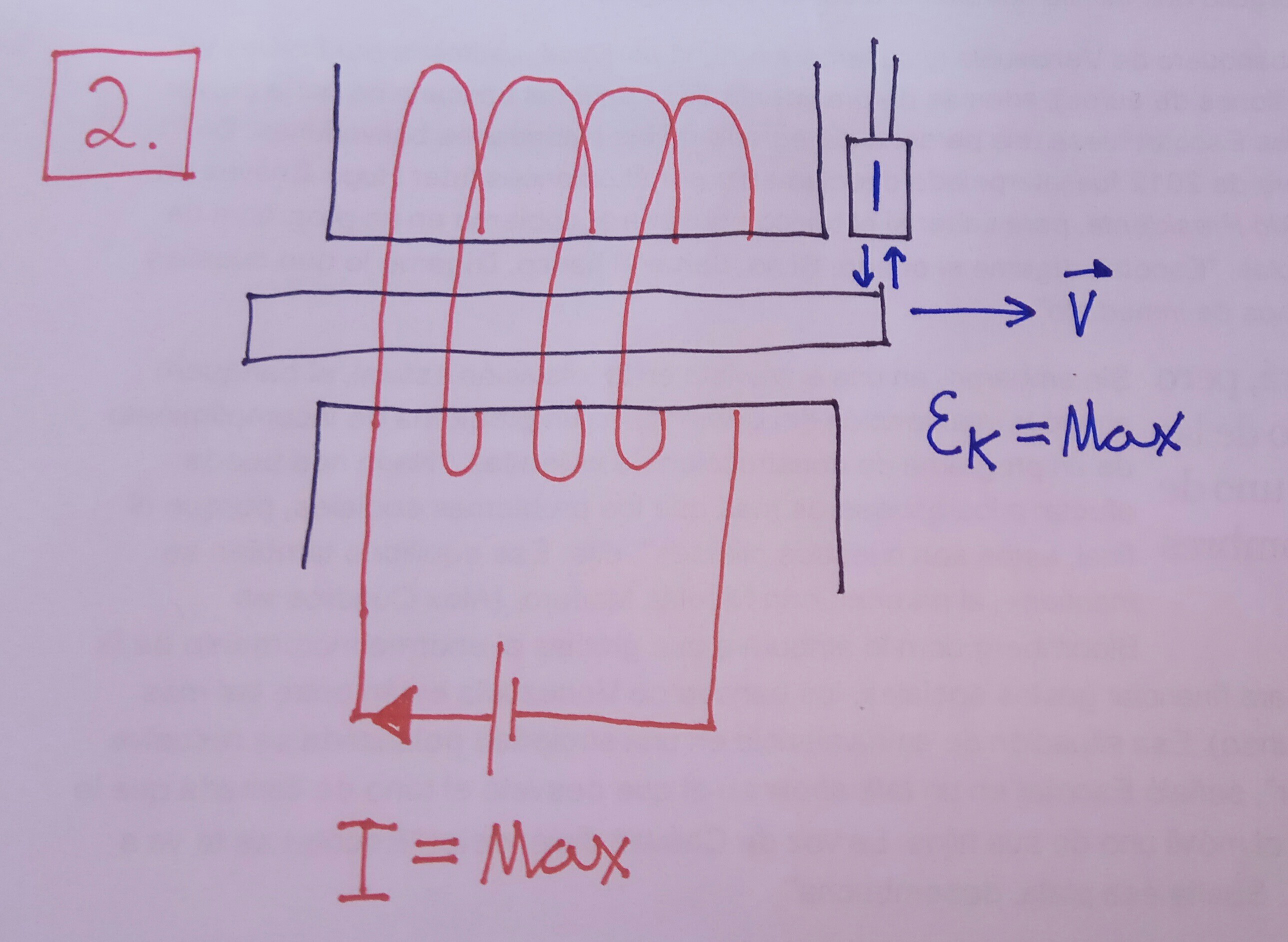
    Then, when the projectile is in the middle of the coil and the kinetic energy is at its maximum, we have to turn off the coil. Because if we keep it on, it will slow down the projectile and will oscillate back and forth. We can detect when it has reached the center using a CNY70(infrared sensor).

    And now, the projectile will exit the coil stage with a good amount of velocity and it's ready to go out of the cannon or to be accelerated again by the next coil stage.

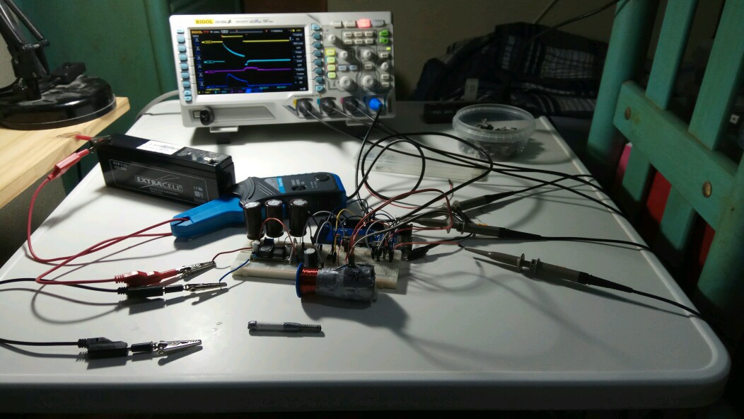
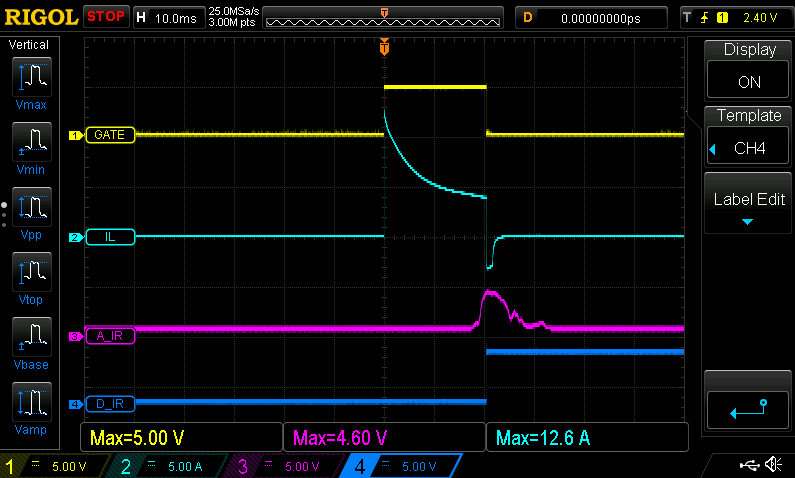
    Here is a shot of the firing process in an oscilloscope. As you can see, current is first applied to the coil, then the CNY70 detects the projectile and the coil turns off.

    • GATE = Gate of the MOSFET.
    • IL = Voltage through the coil.
    • A_IR = Analog output of the CNY70 sensor.
    • D_IR = Digital output of the CNY70.

    And this is the final result of the coil gun:

View all 11 project logs

Enjoy this project?

Share

Discussions

Similar Projects

Does this project spark your interest?

Become a member to follow this project and never miss any updates