Archiving the original V1 board and no-board prototype instructions here.
THIS IS NOT CURRENT
Hardware
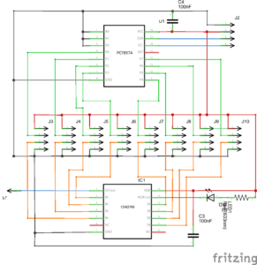
The minimum setup to use this usefully requires
- a PCF8574 or PCF8574A IC
- two HC-SR04 sensors
- two NPN transistors and some resistors to make a NOR gate
- example sketch SonarI2Cv2
![basic breadboard test]() Software
Software
If you are using version 1.6.2 or later of the Arduino software (IDE), you can use the Library Manager to install this library:
- In the Arduino IDE, open the "Sketch" menu, select "Include Library", then "Manage Libraries...".
- Search for "SonarI2C".
- Click the SonarI2C entry in the list.
- Click "Install".
If this does not work, you can manually install the library:
- Download the latest release archive from GitHub and decompress it.
- Rename the folder "SonarI2C-master" to "SonarI2C".
- Move the "SonarI2C" folder into the "libraries" directory inside your Arduino sketchbook directory. You can view your sketchbook location by opening the "File" menu and selecting "Preferences" in the Arduino IDE. If there is not already a "libraries" folder in that location, you should make the folder yourself.
- After installing the library, restart the Arduino IDE.
(note - the above instructions adapted from a Pololu readme)
HC-SR04 I2C Octopus "octosonar"
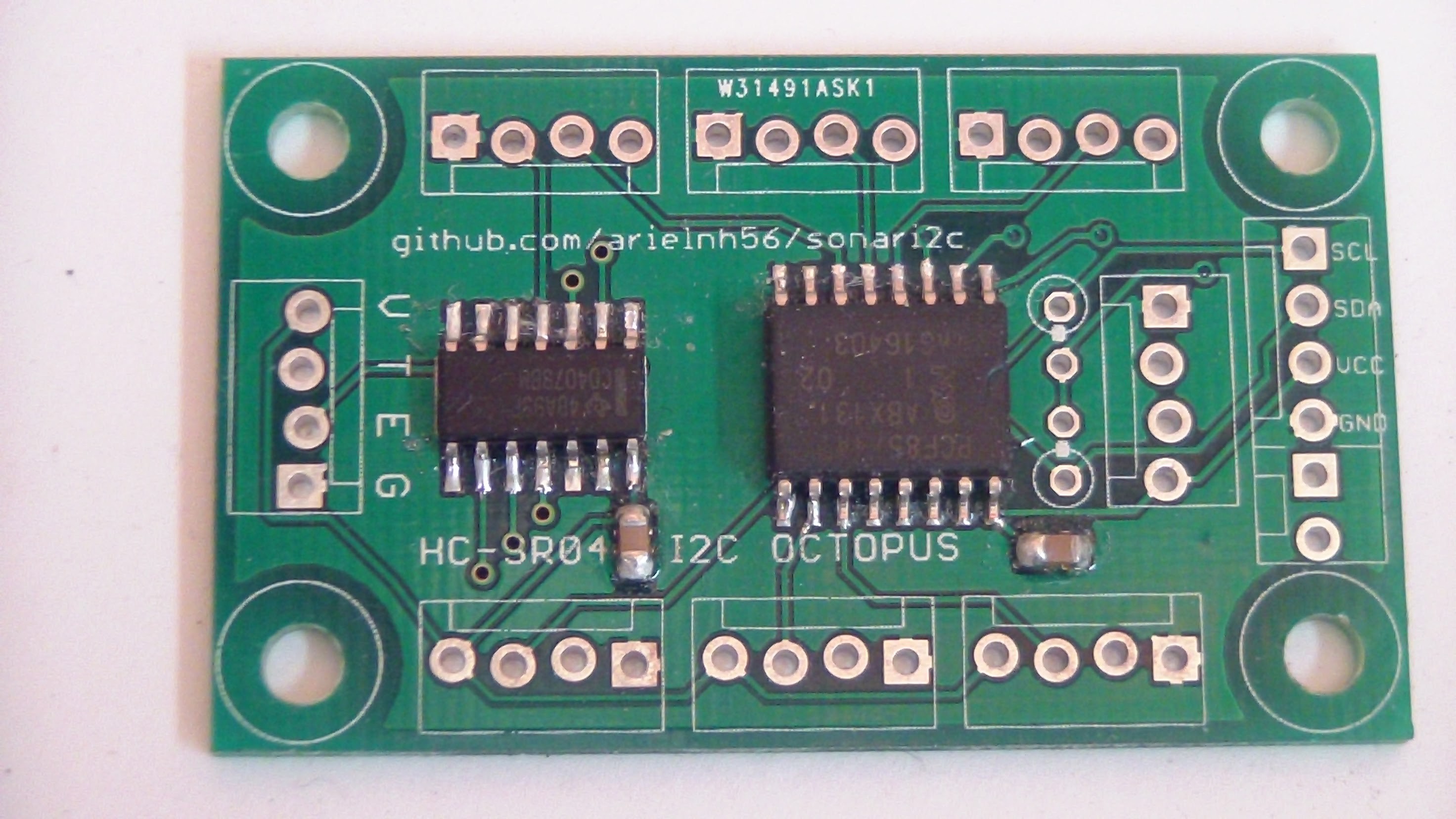
There was enough interest in these that I made up a small batch to sell on Tindie.
To test these without the headers attached, I made up a test-bed on an Arduino proto-shield. This tests all the power pins (the green LEDs), checks the outputs from the PCF8574A and feeds signals into the CD4078 and verifies the output.

There is a minor error on these boards in that the silkscreen "Name" layers are missing so it does not show what port is which. Refer to the image below.

IMPORTANT: There are no pull-down resistors on the Echo inputs. Jumper any unused ports from E to G or you will get very erratic results.
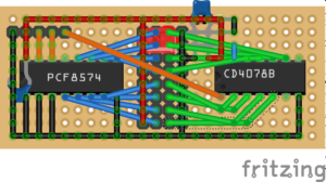
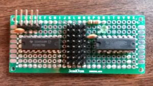
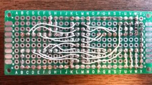
The 8 Port Prototype
Download the current SonarI2C library code on GitHub
HC-SR04 I2C Octopus "octosonar"
There was enough interest in these that I made up a small batch to sell on Tindie.

To test these without the headers attached, I made up a test-bed on an Arduino proto-shield. This tests all the power pins (the green LEDs), checks the outputs from the PCF8574A and feeds signals into the CD4078 and verifies the output.

There is a minor error on these boards in that the silkscreen "Name" layers are missing so it does not show what port is which. Refer to the image below.

IMPORTANT: There are no pull-down resistors on the Echo inputs. Jumper any unused ports from E to G or you will get very erratic results.
 Alastair Young
Discussions
Become a Hackaday.io Member
Create an account to leave a comment. Already have an account? Log In.