 Dave's Dev Lab
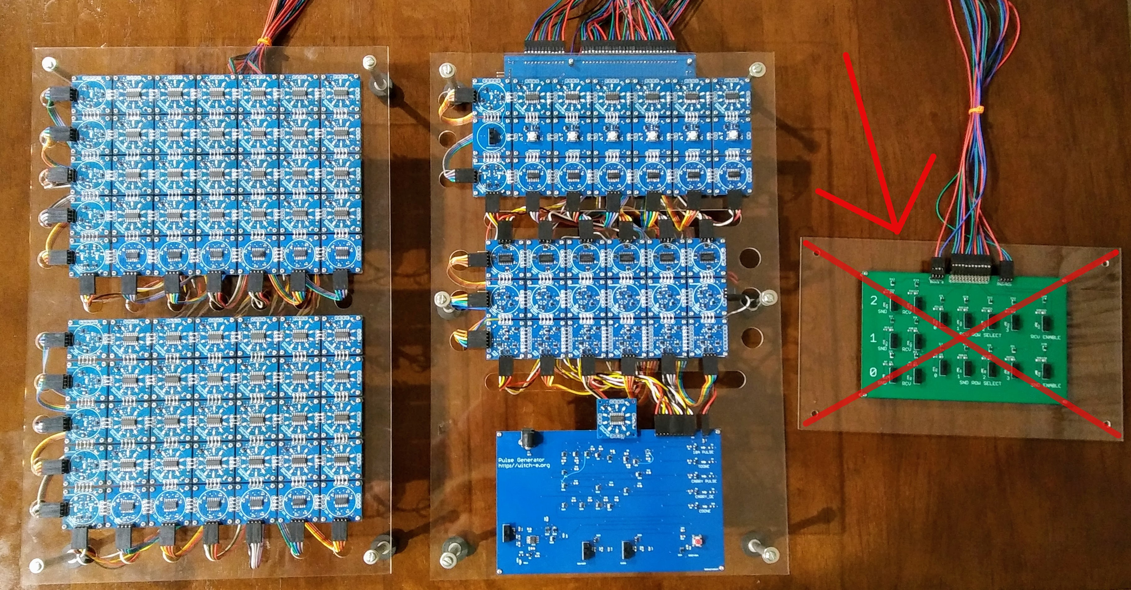
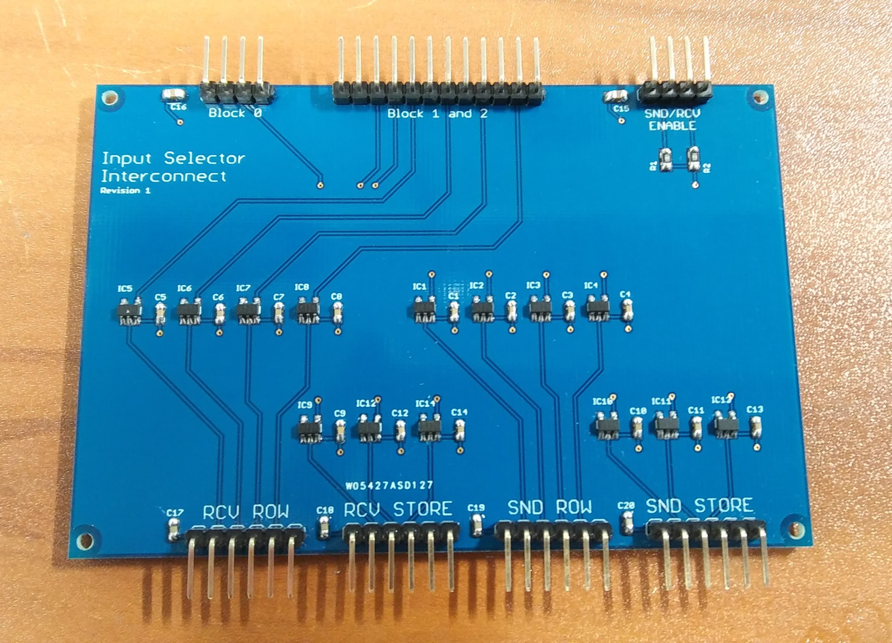
During Phase-2 of the project it was necessary to create a small test board to enable the various functions and memory locations. That board is the "green one" in the picture above. It basically consists of a number of switches that all each of the memory locations to be activated as well as select things like addition, subtraction, and clear functions. To bridge the work done in Phase-2 to the input system built in Phase-3, I need to replace the green test board with a bridge board that will connect the two development phases together. This basic board has some Schmitt triggers on it to clean up the signals from the long wires and then route the signals to separate connectors for each of the input system decoders. It's a super simple board, but it is essential to connecting the two sections together!
Discussions
Become a Hackaday.io Member
Create an account to leave a comment. Already have an account? Log In.