 Dave's Dev Lab
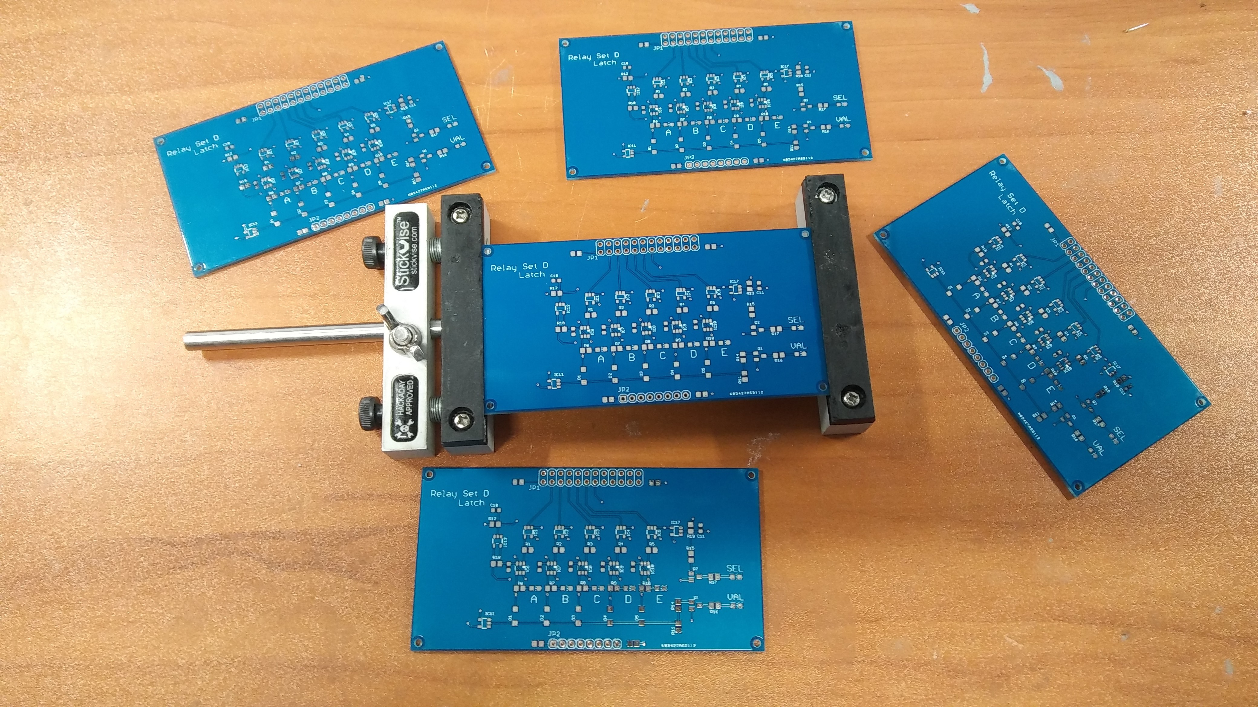
In the original WITCH, the input system uses 5 module blocks know as "Relay Set D". Each Relay Set D, consists of two basic sections. One section is used to latch and "store" a 5-bit baudot code, and a second section to decode the 5-bit baudot code into a "1 of 10" decimal signal. For the WITCH-E design, I've broken the Latch and a Decode sections of the Relay Set D into separate PCBs. For me to test the keypad, keypad encoder, and input sequencer, I need to have 5 of the Latch PCBs assembled and tested. Looks like I have my work cut out for me this weekend....
Discussions
Become a Hackaday.io Member
Create an account to leave a comment. Already have an account? Log In.