 Dave's Dev Lab
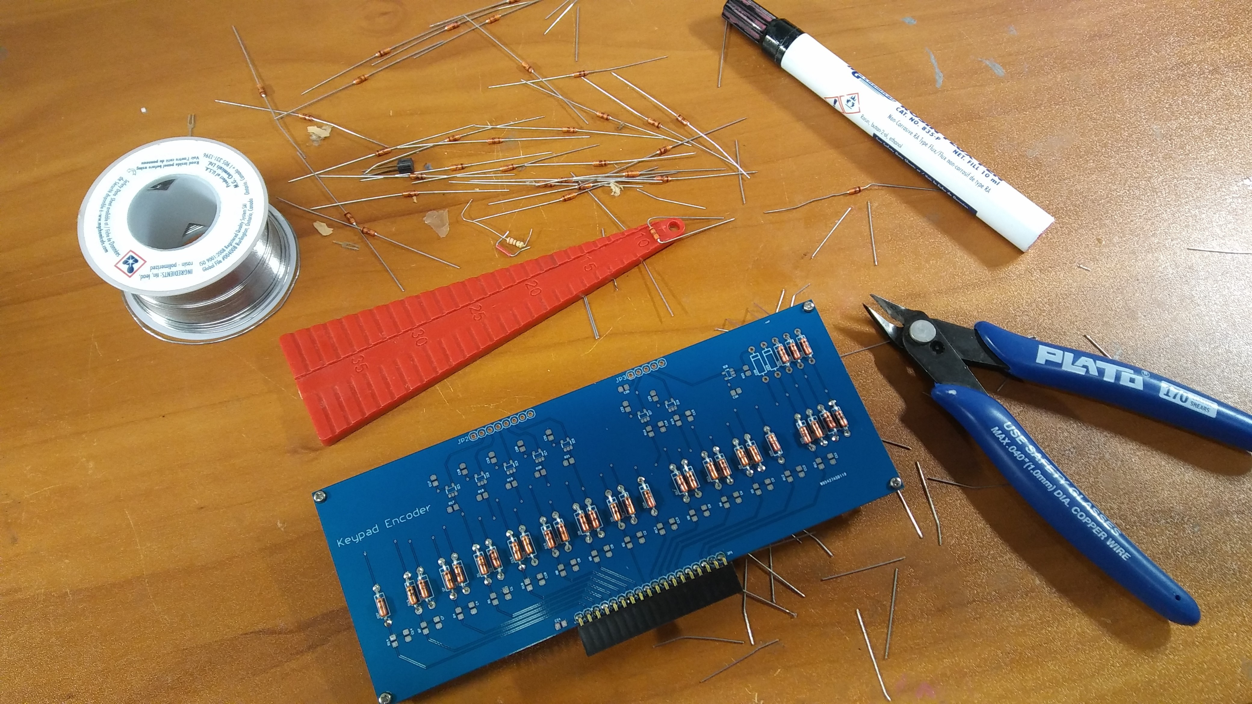
Well it's been a while since i had use for my "bending template"! I took a break from my "day job" work today to assemble the new keypad encoder. I again used the vintage diodes as discussed in an earlier log ( Keypad Encoder ). I kind of regret using them now as they make the board a lot bigger than it really needs to be, but it does add a nice look to the overall design. The keypad encoder breaks the key encoding into one connector that goes to each of the latches, and a separate connector for the reset, execute, and "key-up" signal. During the last round of integration testing ( You WILL be integrated! ), I realized that the keypad and the encoder really need to be close together, so instead of using male headers with female cables, I replace the male header with a female header. This will allow the two boards to be easily connected together with minimal wasted space. Back to bending diodes..... where is Bending Bender Rodriguez when you need him?
Discussions
Become a Hackaday.io Member
Create an account to leave a comment. Already have an account? Log In.