Dave's Dev Lab
-
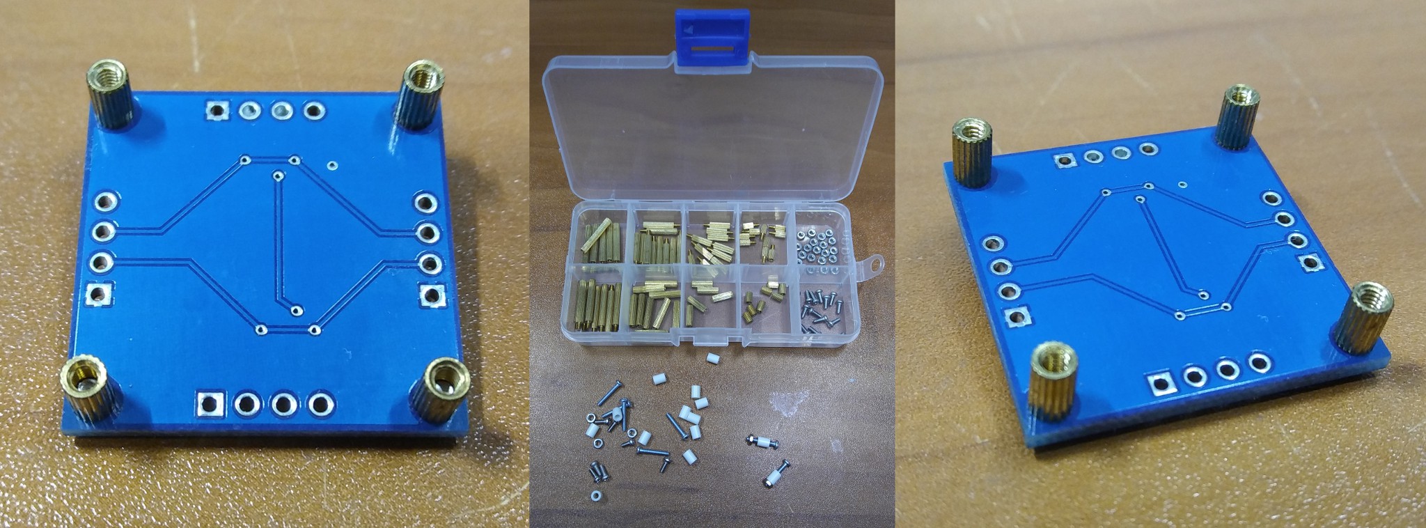
Getting Screwed: Finding Mounting Hardware
09/20/2017 at 00:27 • 1 comment![]()
For a project like WITCH-E, it isn't always "fun and games" with the electronics and research. Practical matters need to be addressed such as: How the heck do I mount all of these PCBs onto some acrylic? From a design perspective I wanted to use some very small screws to take up as little pcb space as possible. I also needed the method to be both easy and inexpensive as I would need mounting hardware for roughly 200 pcbs. My first thought was to purchase some off-the-shelf M2 screw kits with standoffs, then I did the math! Each box only contained 10 of the screws and standoffs that I wanted to use and at a price of around $6USD, that made each standoff with matching screw cost $0.60USD. Plus I would have to purchase 80 kits! So I continued to look. I found some inexpensive teflon spacers, and some 13mm long M2 screws at a decent price and decided on using them along with a matching nut. Well that was the plan... until I actually tried to use them. Threading the screw through the holes on each pcb while holding on the other screws and making sure the teflon spacers stayed in place was nearly impossible. So once again I went in search of mounting hardware. My first thought was to visit McMaster-Carr's website to see what was available. As recently posted on Hackaday.com (https://hackaday.com/2017/09/13/noobs-guide-to-mcmaster-carr/) McMaster-Carr has just about any kind of screw, nut, and mounting known to man in single quantities, and they had what I was looking for. Unfortunately, just like the kits, the M2 standoffs and screws were WAY too expensive to consider in larger quantities, so my next step was to try Ebay. After tweaking my search key words, BINGO! The pricing was much better, around $0.10USD for two screws and a standoff. So the moral of this little post is that buying the right mounting hardware can be tricky and that you have to be careful not to get screwed while trying to buy screws...
![]()
-
Dekatron Simulator Evolution
09/19/2017 at 01:55 • 0 comments![]()
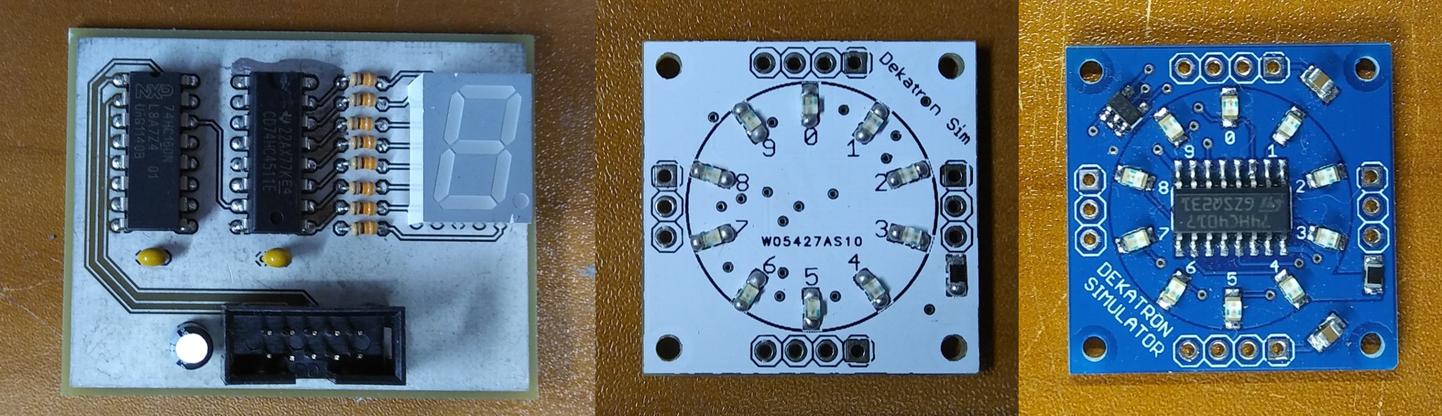
The essential technology at the heart of the Harwell WITCH is the Dekatron. The Dekatron, as the name implies is basically a decade counter, and while many variations of the Dekatron are still available via places like Ebay, using them in the WITCH-E project was not economical, not practical, and generally not safe due to the high voltages needed to operate them. So what I needed was something that could replicate the functionality of a Dekatron. Something made with modern components, something that would be inexpensive to build (since I would need to build a LOT of them!), and something that was easy to assembly by hand. The first task was to find components that matched the functionality of the Dekatron as they were used on the WITCH. Dekatrons support the ability to increment their stored count as well as decrement the stored count, however in the WITCH the Dekatrons were only used to increment the stored count, so I focused on finding something that only supported incrementing. My first prototypes used a 74HC160 decade counter with BCD (Binary Coded Decimal) output connected to a 74HC4511 BCD to 7-segment display. This version was rather large, used two chips and needed 8 resistors, plus it just didn't "feel right". The 7-segment display gave a really good educational aspect to the design, but just didn't have the same "feel" as the circular Dekatrons, so I went back to the drawing board. Again since I only needed the ability to increment, I selected the 74HC4017, a TTL version of the popular CMOS CD4017 decade counter. On the first revision using the 74HC4017, I placed the LEDs on the front, with the 74HC4017 on the back of the board, making it a two sided assembly. My thinking was since I was hand assembling these, having a two-sided assembly wouldn't matter much... boy was I wrong! It really complicated the assembly process and made it very time consuming. So on the next revision of the design, I went with all single sided assembly. While having the 74HC4017 in the center does take away from the aesthetics on an individual PCB, the overall results for an assembled group are generally geeky enough to over look this minor issue...
![]()
-
It's All About the Datasheets!
09/17/2017 at 20:55 • 3 comments![]()
In the effort to translate and convert the WITCH design from using Cold Cathode Valves (aka tubes) into modern components, it was essential to understand how each of the valves worked and how they were being used in the system. As someone who grew up in the age of the transistor, I was completely unfamiliar with practical applications of using valves. This is where the engineer in me kicked in. The first order of business was to find datasheets on every component I could identify. The WITCH schematics and maintenance logs had very good details about the model and type of devices being used. I quickly found on the net The Valve Museum. Most of the parts I was looking for were documented there with datasheets and pictures! Now with datasheets in hand, I was able to start working backwards on how exactly these engineers created a working computer from "stone knives and bearskins"!
EDIT: pictures and pdf datasheets are available via the WITCH-E Project github repository under datasheets
-
Getting Started! The WITCH Bootrom
09/17/2017 at 02:32 • 1 commentOne of the fundamental aspects of the WITCH-E project is to gain a better understanding of the the original WITCH and document it. Unlike many other retro computing projects where thousands, or tens of thousands of the original computer still exist, there is ONLY one WITCH. With that in mind, I can't really ask to "poke around" on the original, and randomly hook up logic probes, so I had to use a different method for reverse engineering the WITCH. Most of the details I have learned about the machine are from maintenance documents/logs, schematics, and pictures of the machine. One of the research areas I was keenly interested in is how the WITCH initially started up. Modern systems often use Read-Only-Memory(ROM) that contain the systems initial instructions, but what did the WITCH use? I made a short little video of how I figured this little item out, and replicated the functionality....
-
Prototype is as Prototype does...
09/16/2017 at 00:25 • 1 comment![]()
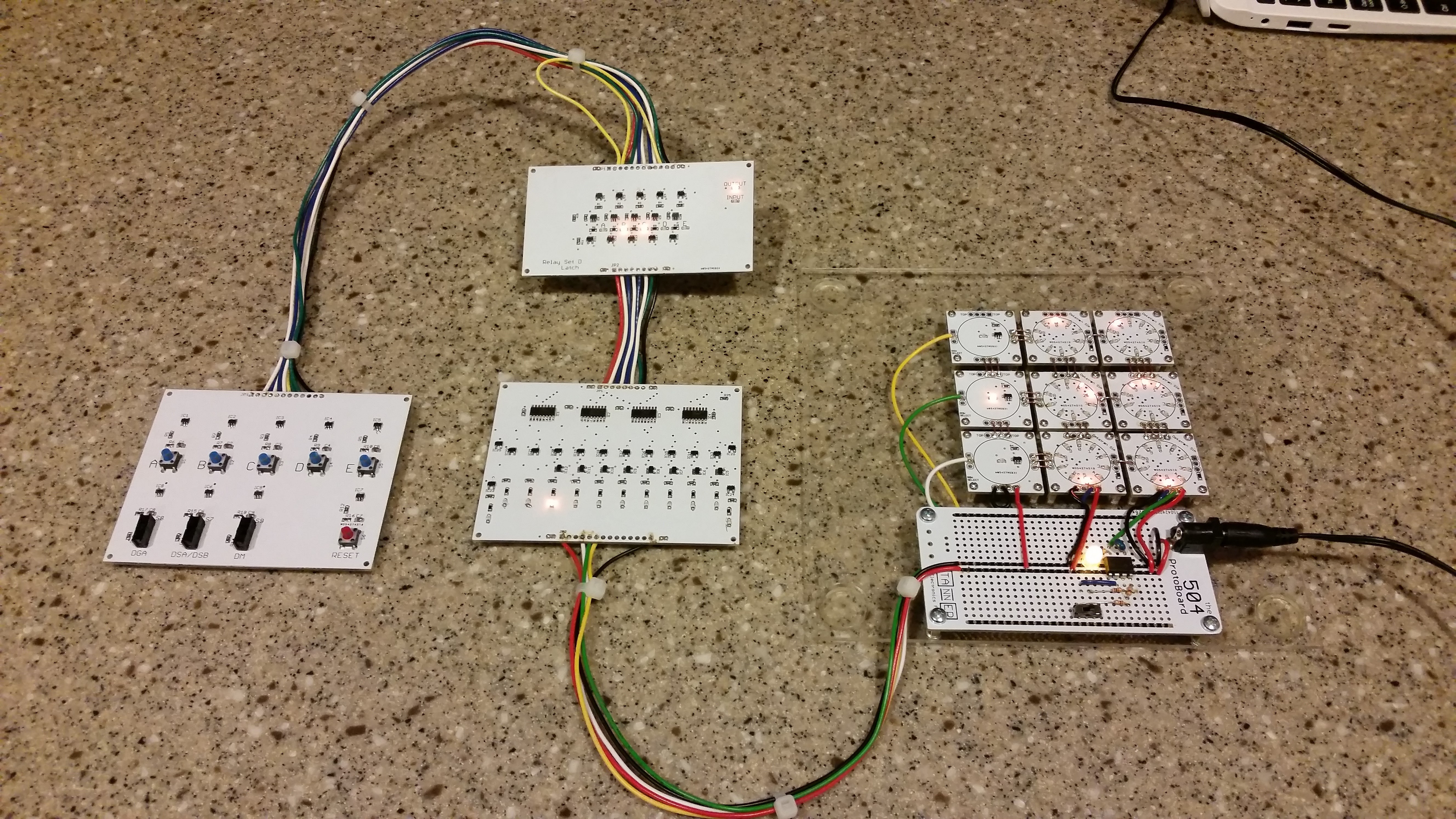
In the normal business model of creating electronics and products in general, prototyping plays a really strong role in "getting it right". One thing that I've really taken advantage of during the development process for the WITCH-E project is doing smaller compartmentalized prototypes. These "smaller and simpler" prototypes can be very valuable in moving forward with a complex design. What I mean by this is instead of starting off with the idea that this particular section would be designed and prototyped specifically to fit into the project, I designed it to be as simple as possible, simple to debug, simple to assemble, and simple to modify. The prototype pictured above contains several very basic pieces of the WITCH-E in smaller form. This includes a simple 5 bit input block, a 5 bit latch, a 5 bit decoder, a 3x2 dekatron matrix, and a 555 based pulse generator. This simple little prototype setup allowed me to test and debug these sections without having the dependency of the entire system being integrated and working. Also due to the very nature of the prototype, I was able to do white-wire fixes, solder test leads on components, and generally 'hack' the modules without concerns of damaging the full system. Moral of the story here is "Prototype is as Prototype does!", which means when a design gets complicated, some times the best method is to get simple...
-
All Your Sequence Belong to Us!
09/15/2017 at 02:27 • 1 comment![]()
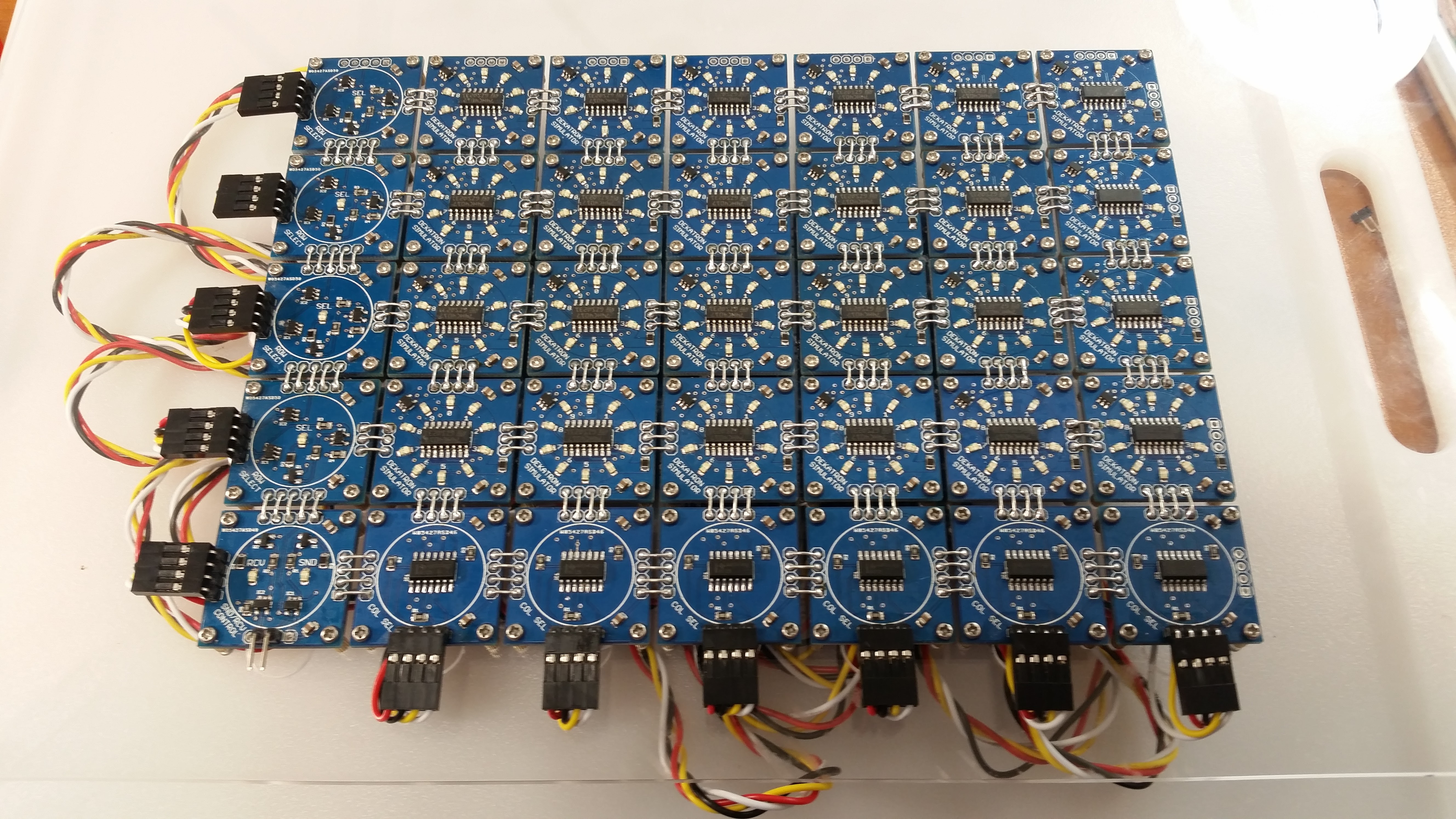
After a bit of hiatus on the project, I started back on the next phase of the project which is to expand the input system. Currently I have some test boards to select the "Send" and "Receive" locations as well as selecting the actual function to be executed. This will be replaced with a keypad and eventually also a "Paper Tape Reader". The input sequence consists of entering 5 digits via the keypad, and then pressing the execute button. I have a 4017 decade counter that steps through each one of the inputs and then kicks off the calculation sequence. The first version of the board was design almost in a "vacuum" as I really didn't have an mental picture of how I was going to connect all of the signals to the board or where the board would physically fit into the system, I was mainly concerned with replicating the original functionality in the WITCH. After assembling the prototype and doing some debugging, I realized that the reset on the D Flip-Flops was an active low while the reset on the 4017 was an active high! DOH! After scabbing on an inverter the design worked as expected. I spent some more time looking at exactly how I would be routing the cables and made some connector changes for the next revision which just arrived and is ready for assembly!
![]()
-
What a 65 Year Old Computer can Teach Us Now
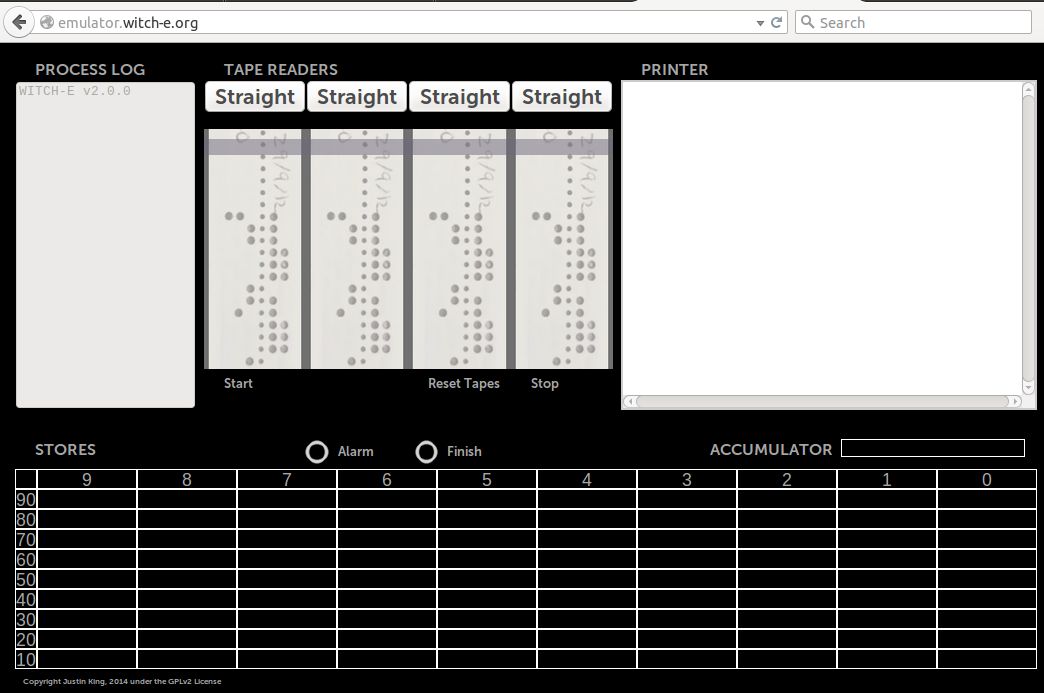
09/09/2017 at 15:45 • 0 commentsPart of the WITCH-E project's early goals was to create a web based emulator for the WITCH. This would allow us to study how to program the machine and to also understand some fundamental ways of how the machine operated. I met Justin King at an open source conference back in 2014. Justin was 11 at the time and was interested in taking on the challenge of creating the emulator in javascript. I was a little skeptical, but gave him some of the specifications. Long story short: a year later we had an emulator and Justin did a presentation at the 13th annual Southern California Linux Expo (SCALE) in 2015 on what he learned during the project! Justin did an incredible job at dissecting the programming environment and recreating the functionality! The emulator source is available via github at https://github.com/prpplague/witch-e
![]()
-
WITCH-E Presention At TNMOC
06/29/2017 at 18:13 • 0 comments![]()
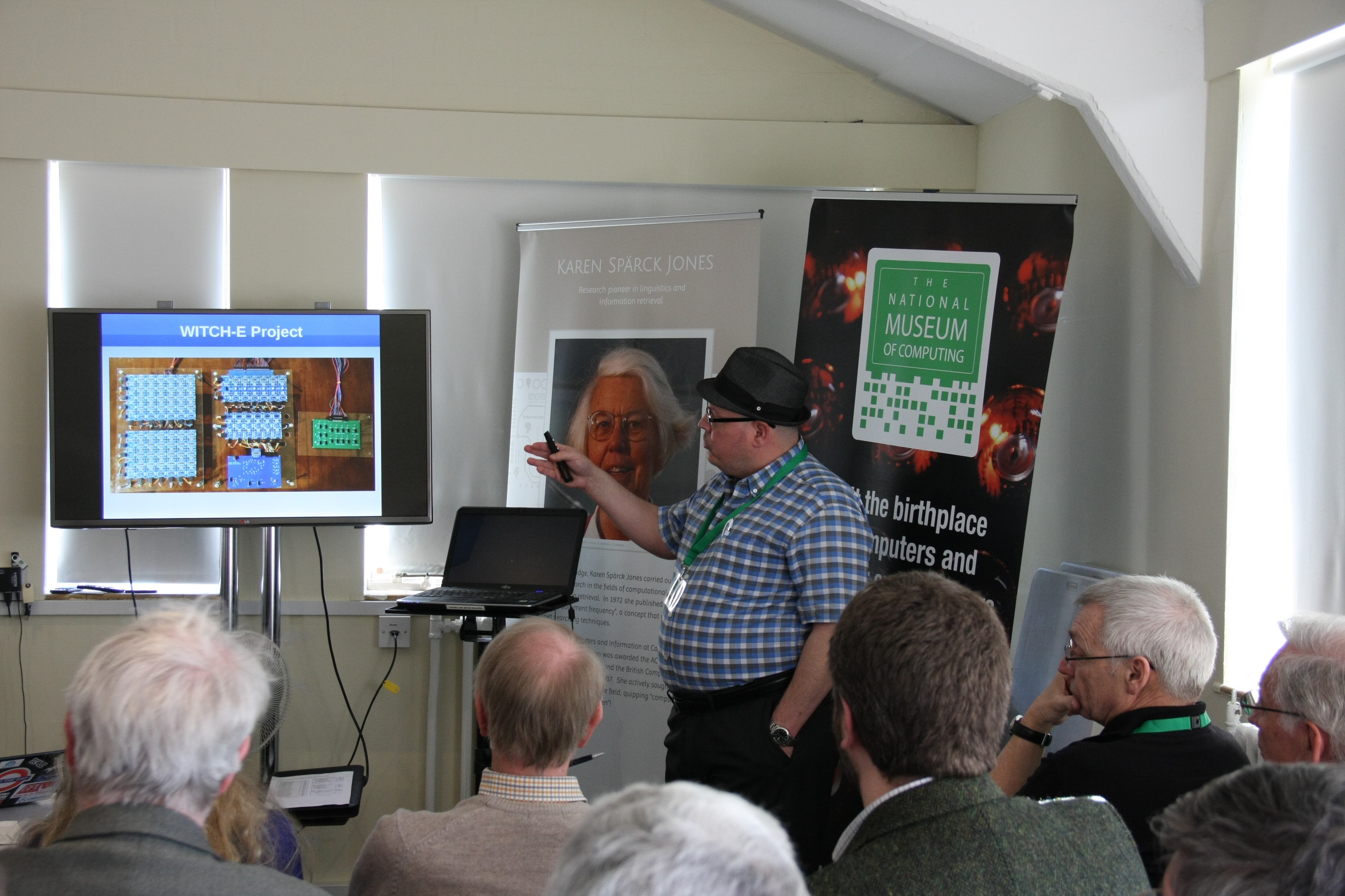
Dave Anders (prpplague) doing a presentation on WITCH-E at the National Museum of Computing located at Bletchley Park, England.
-
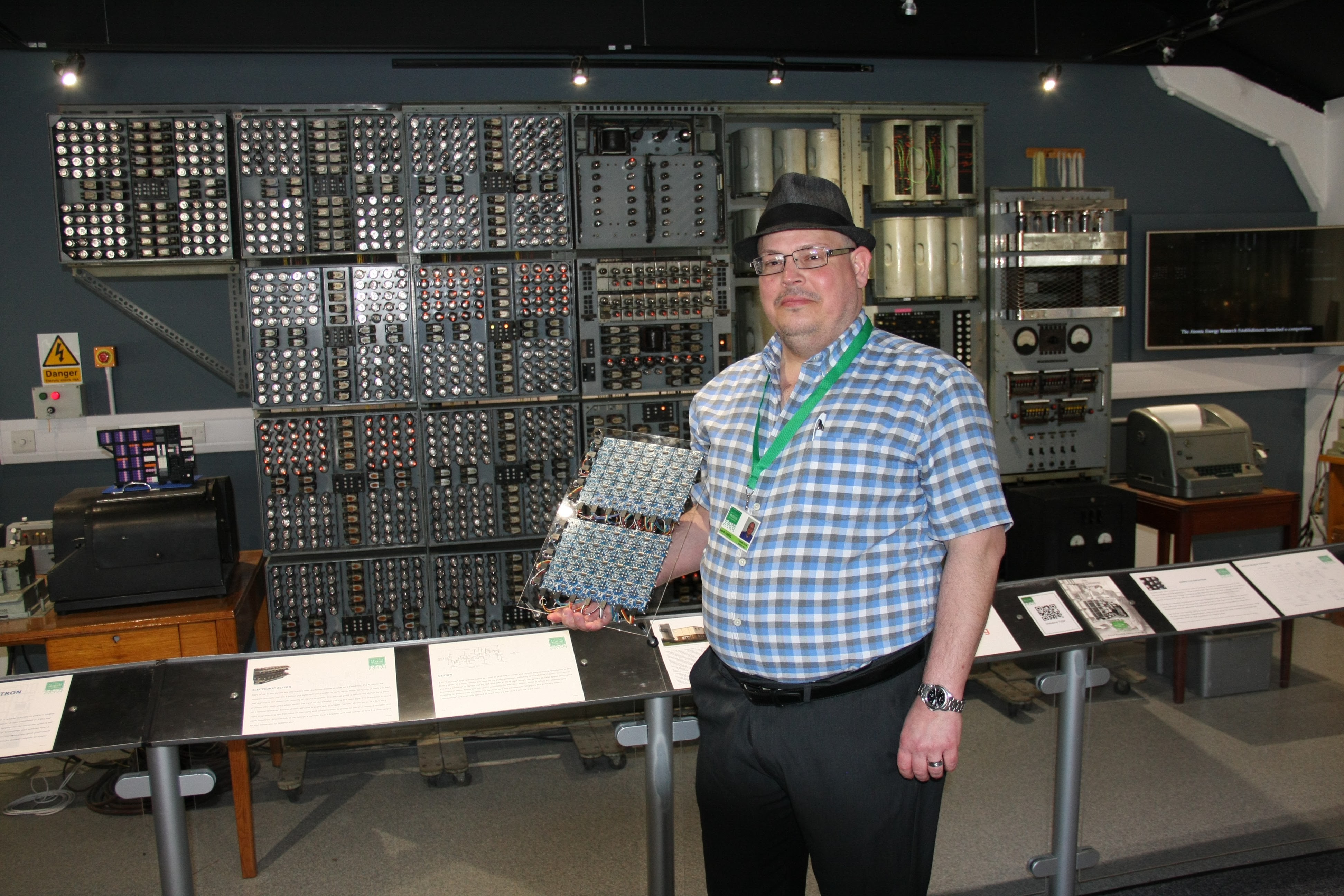
WITCH-E with WITCH
06/29/2017 at 18:09 • 0 comments![]()
-
Last Minute Tests and Tweaks
03/17/2017 at 22:04 • 0 comments![]()
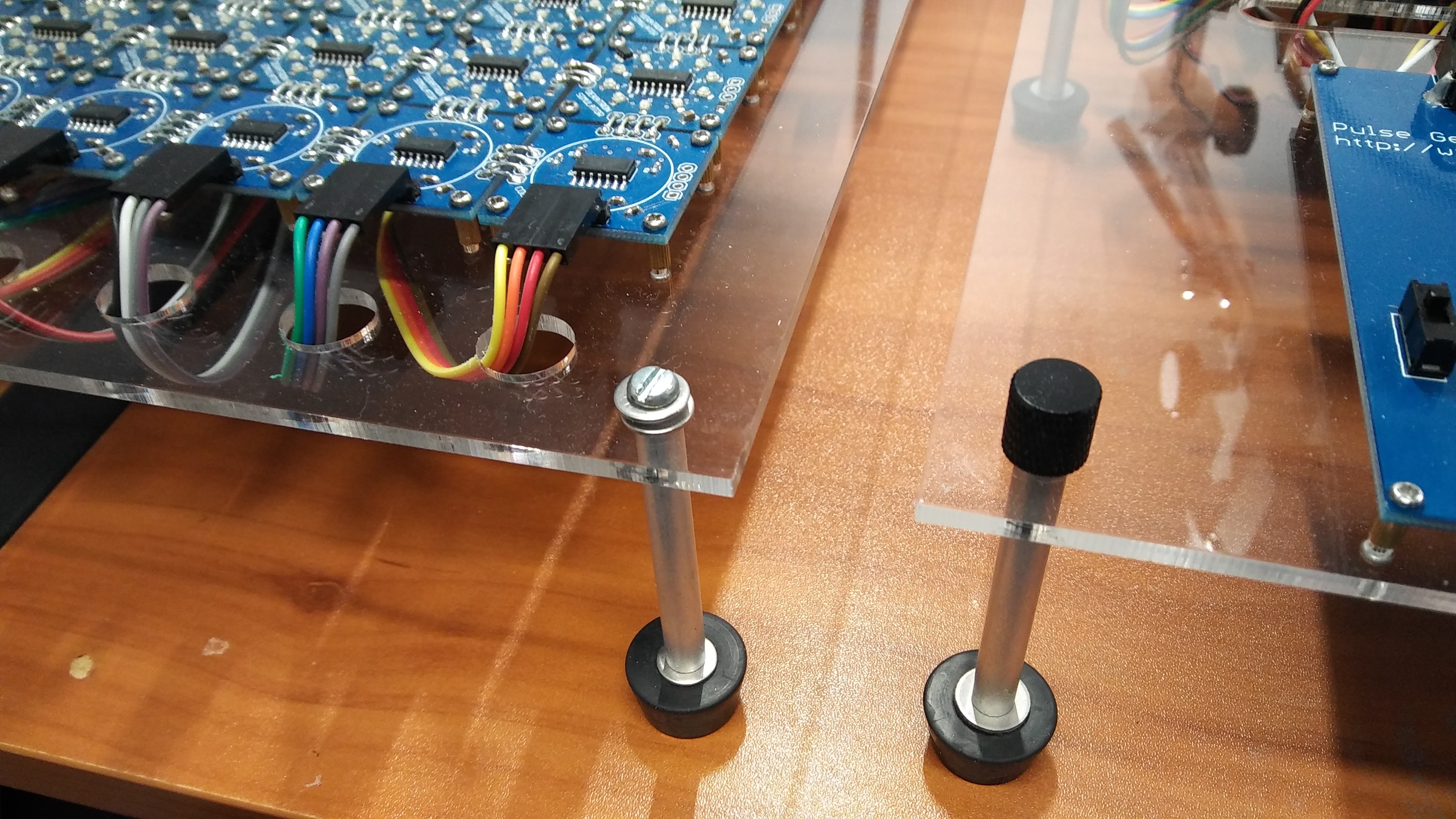
so i am continuing to get ready for the trip to the National Museum of Computing to demo the WITCH-E prototype! as the WITCH-E is mean to be easily disassembled and transported, i noticed that the flat head screws on the left were a little time consuming and difficult to assemble, so i've replaced them with some anodized aluminum thumbscrews on the right. these are much easy to use on the fly and make reassembly a snap! they also look a lot better than the plain old screws....
WITCH-E Decimal Based Computer
Document and create a modern replica of the Harwell Dekatron computer known as the WITCH