Dave's Dev Lab
-
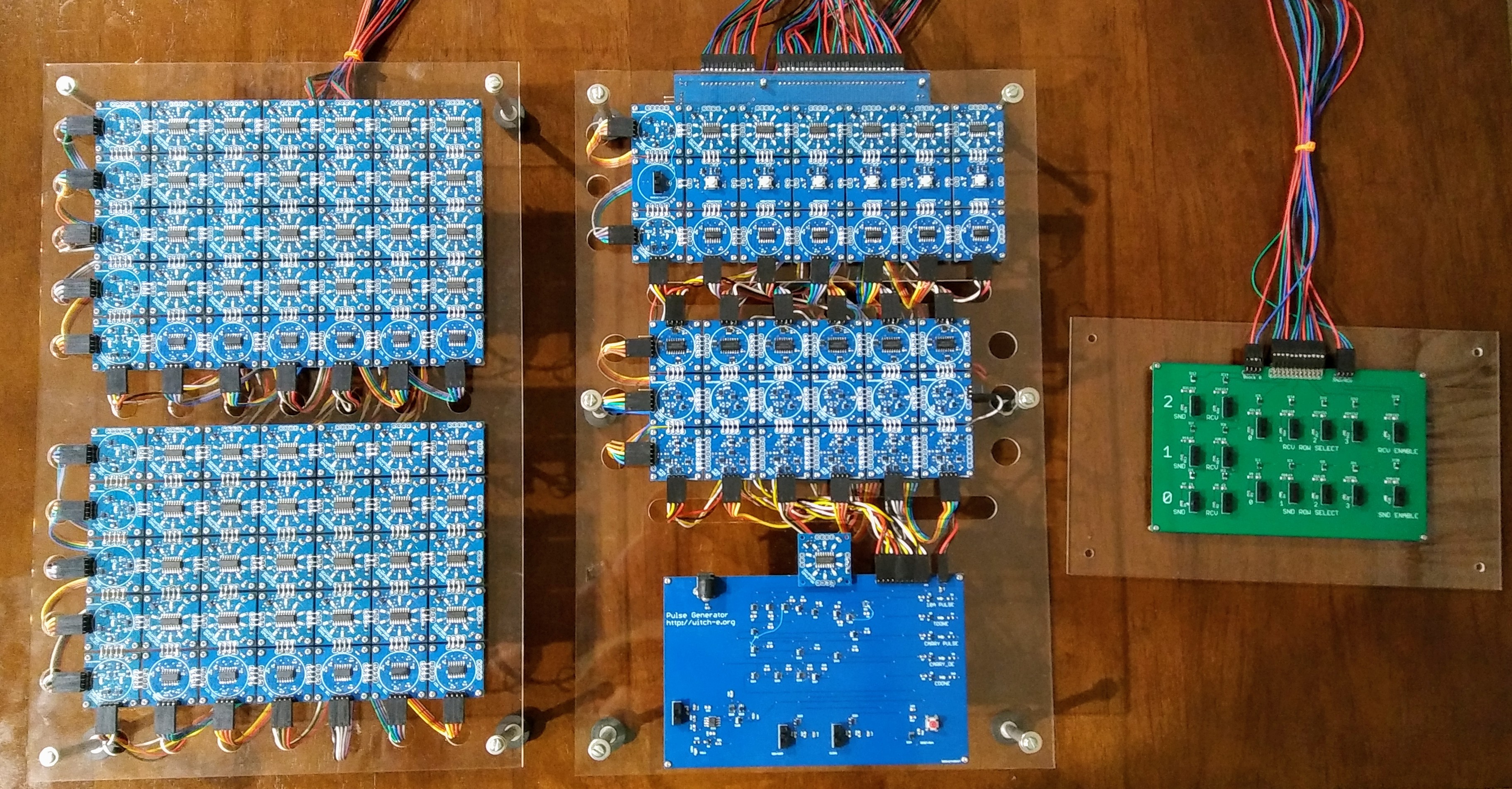
New Acrylic and Wiring
03/10/2017 at 00:51 • 2 commentsWITCH-E has been reassembled with the new acrylic from Ponoko.com and new wiring. I've made the panels smaller and specifically designed them to fit into a Pelican hard case for traveling. the single green board to the side is the register select test board, and since it is a test board, i've used green soldermask to distinguish it from the blue portions of the actual WITCH-E system. As more of WITCH-E is completed, panels will be added to the right where the register select test board is located. we are all set for travel to the National Museum of Computing for the first public demo of the WITCH-E!
![]()
-
Help Fund the National Museum of Computing
03/05/2017 at 01:34 • 0 commentsPlease Consider Helping
Please consider donating to my fundraiser for the National Museum of Computing! I am matching donations to $1500USD. We have a shared computing history and we need to help preserve it as well as keep computers like the Harwell WITCH on display and functional! If you have questions about how the funds are spend or general questions about the museum and it's mission, feel free to contact me directly at danders.dev@gmail.com
thanks! -
Your Wiring is a Mess!
02/27/2017 at 02:28 • 0 comments![]()
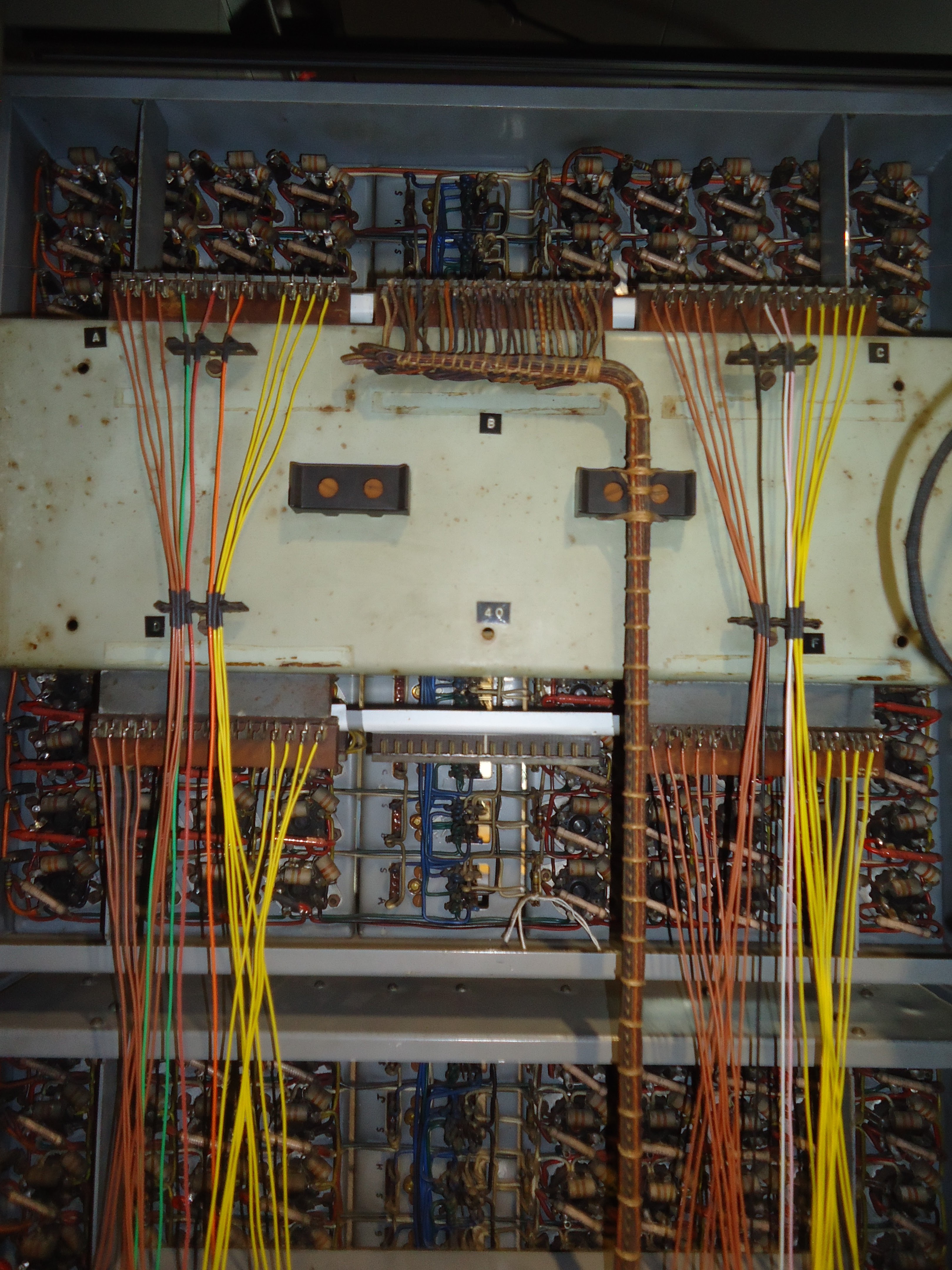
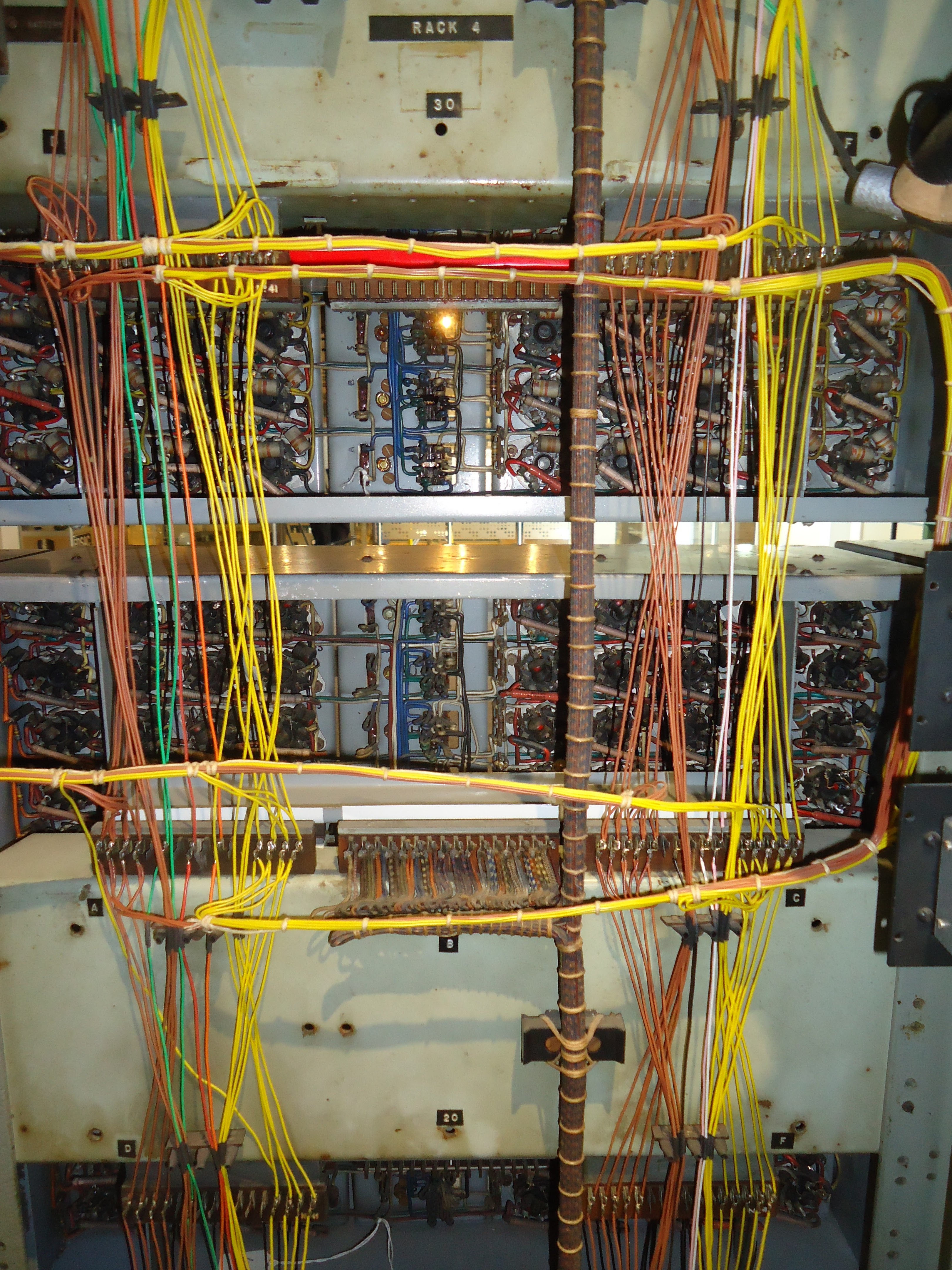
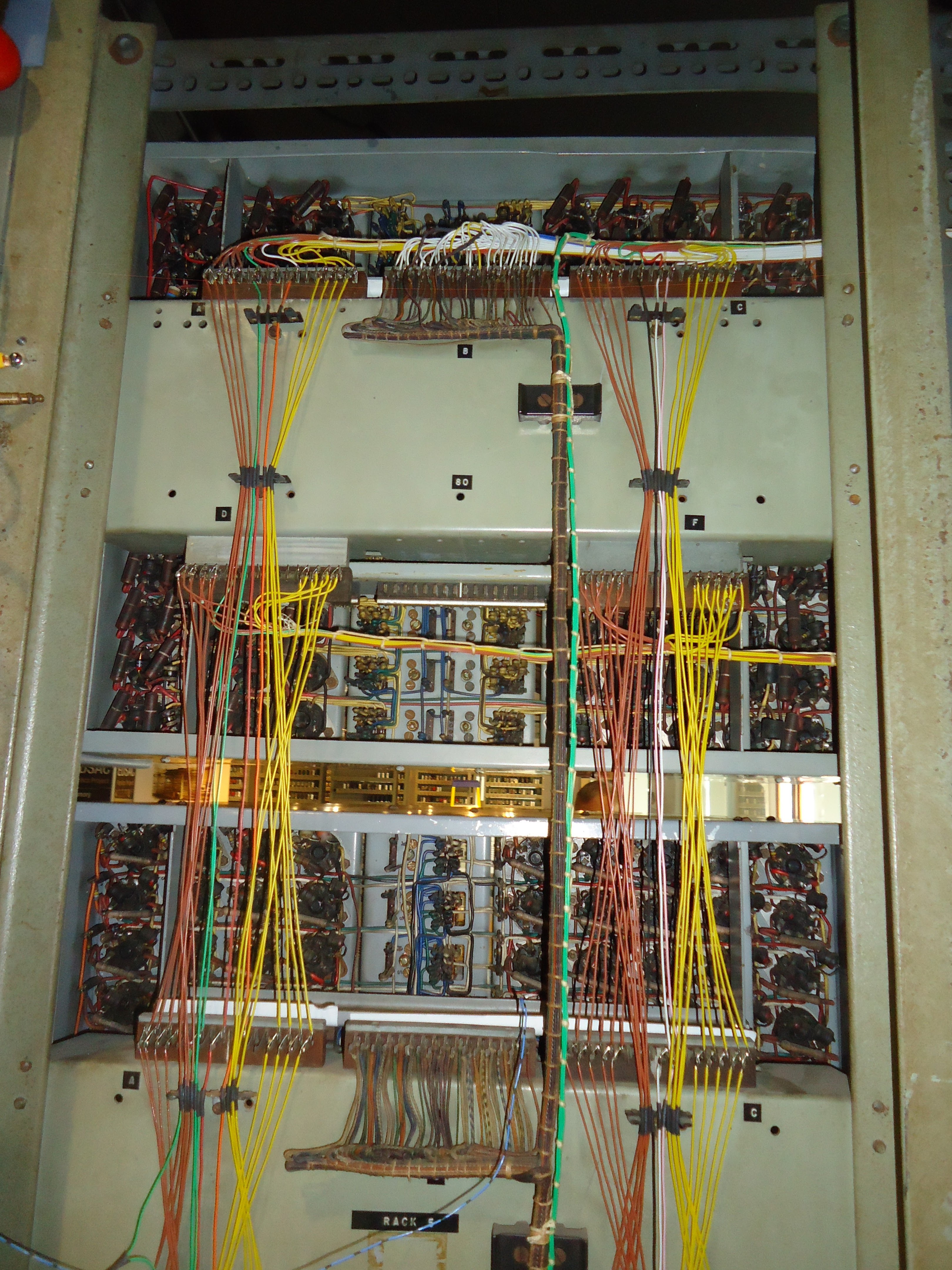
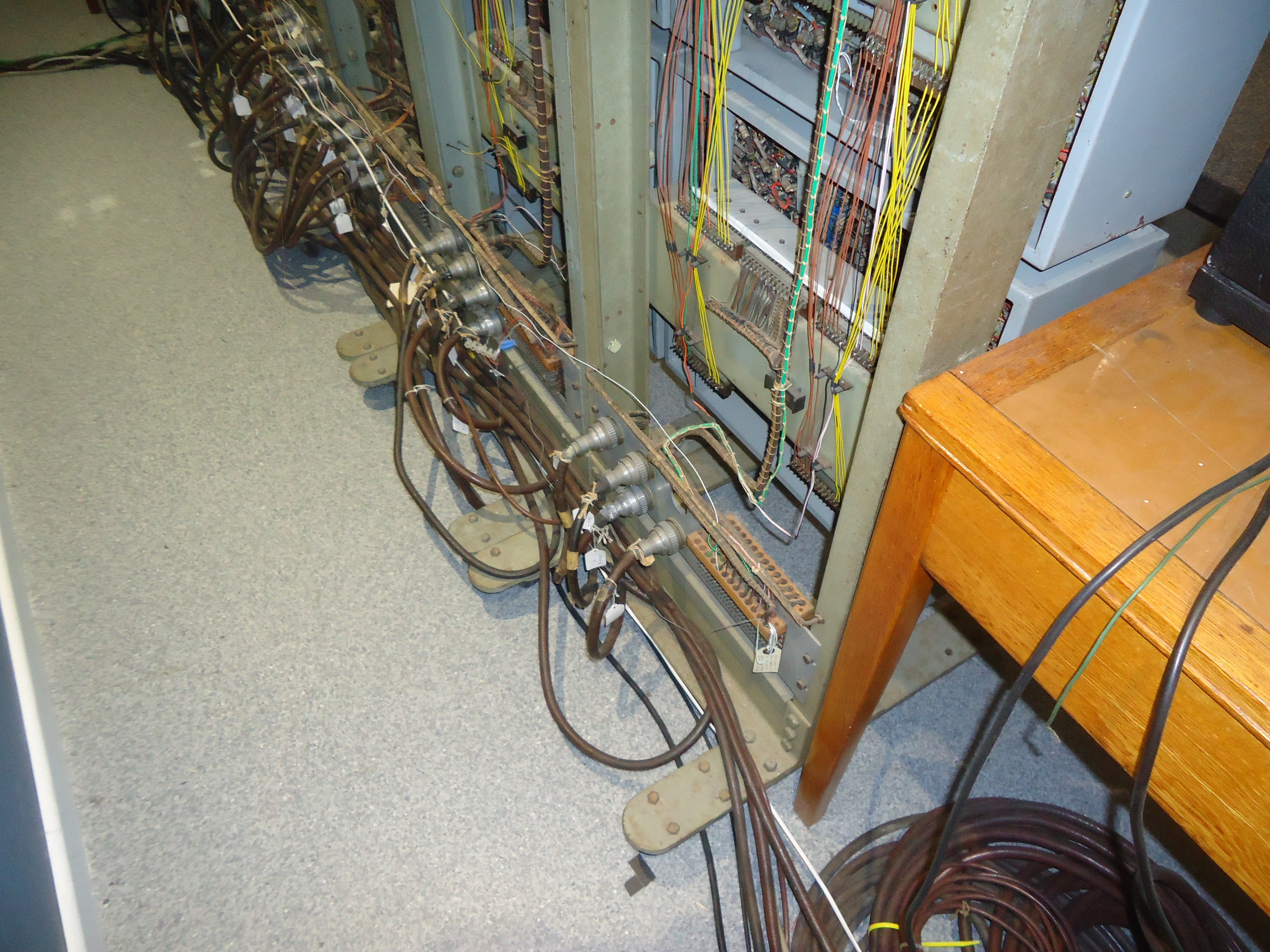
In the fall of 2015, on a dull grey Sunday morning in Block-H of Bletchley Park, I was afforded a great honor. Part of the WITCH-E project is to document as many aspects of the Harwell WITCH as possible, and one of the things I found absolutely no information on was how the wiring on the back side of the WITCH was handled. On this particular Sunday morning, prior to the National Museum of Computing opening to the public, I was allowed to take detailed pictures of the back side of the WITCH. Using this information along with the original schematics, I've replicated the "Interconnects" in generic fashion for the WITCH-E. Here are some of the photos of the original WITCH:
![]()
![]()
![]()
![]()
NOTE: Pictures are used with the permission of the National Museum of Computing for Non-Commercial purposes: Creative Commons CC-BY-NC 4.0
-
It Helps If You Know Your Schmitt!
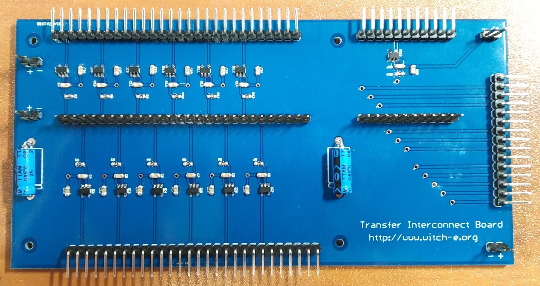
02/24/2017 at 22:41 • 0 comments![]()
I took a quick break from "day job" work to solder on the headers for the new Transfer Interconnect Board. This first revision of this board was simply connections between the headers with no components. After working with the original design for a while and doing some scope captures it was pretty clear that i was getting a lot of signal noise and the rise/fall time of the signals was not within the required ranges for the 7400 series devices that were being connected. With that in mind i did a revision of the design adding some non-inverting schmitt triggers to the the design. oddly enough i was preparing the log post when i realized that Hackaday.com had a new post today about using schmitt triggers. The article called About Schmitt (Triggers) , has a great overview of exactly how adding schmitt triggers to this design helps with both the noise and rise/fall times of the signals.
-
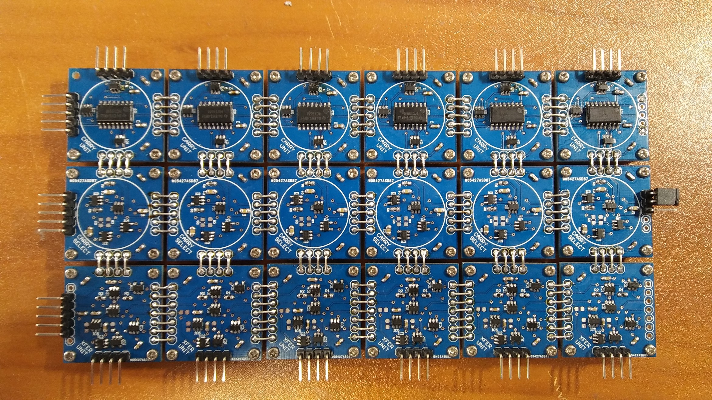
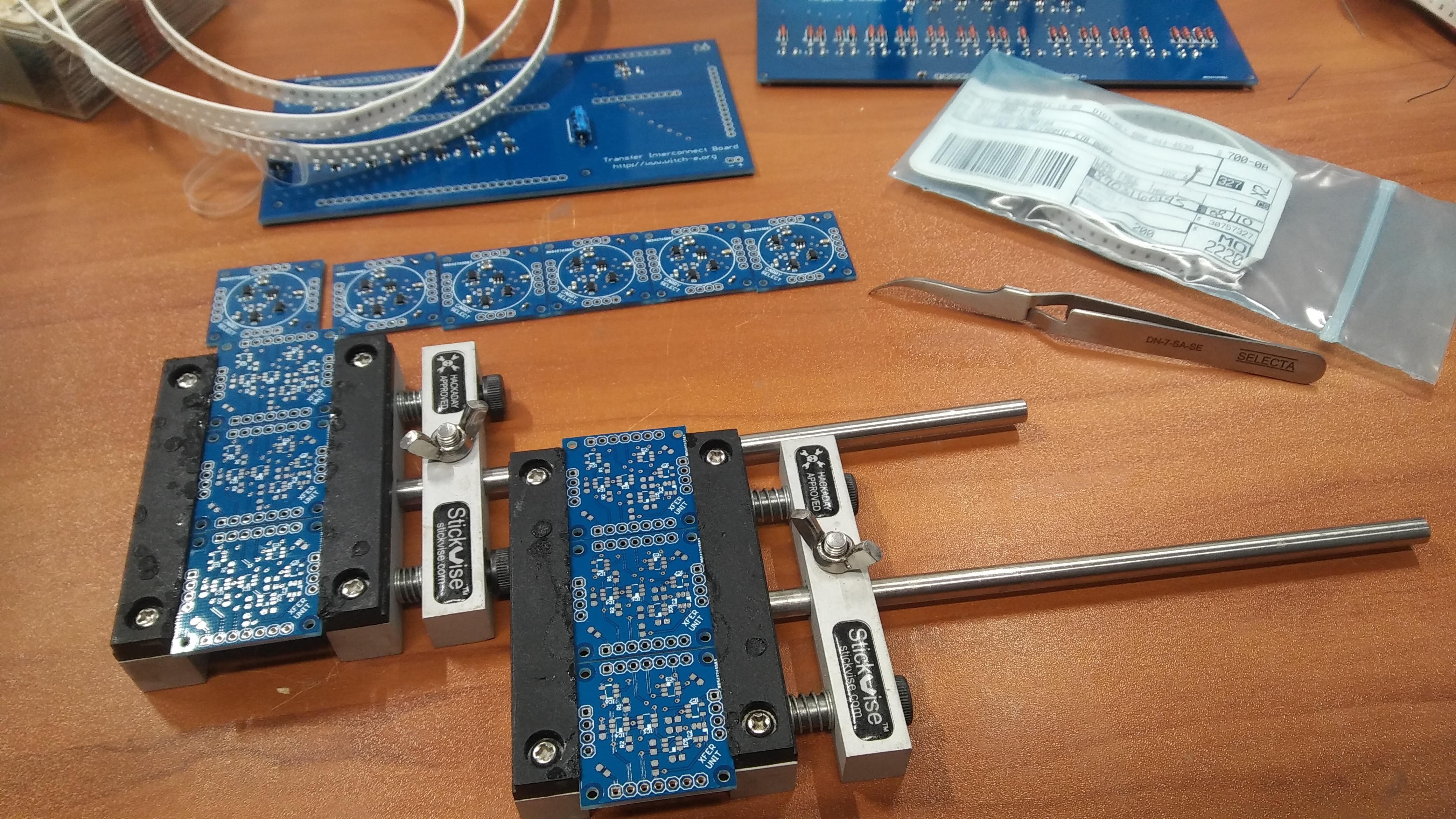
Fully Assembled Transfer Block
02/24/2017 at 21:25 • 0 commentsI was able to complete the assembly of the transfer block last night. the transfer block includes the Transfer Unit, Carry Select, and Carry Unit. each of the modules are soldered together with wire between the 0.1" headers and mounted with M2 screws with 5mm brass standoffs....
![]()
-
Beware of 'Simplified' Schematic Diagrams
02/24/2017 at 02:07 • 0 comments![]()
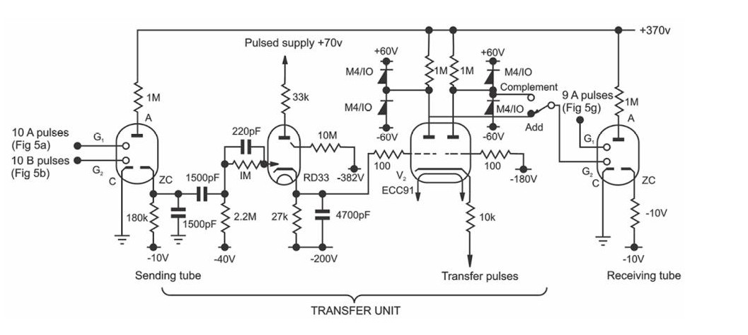
So i have the latest revision of the transfer unit modules assembled. this is the fourth edition of this module as I've slowly been able to break down more and more of the original schematics for the WITCH and understand how they are actually translated into modern components and functionality. i started off with this simplified diagram from the Electrical Engineering magazine article on the WITCH:
![]()
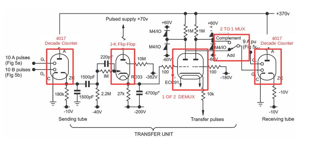
My initial attempt at the transfer unit was to simply identify the functionality of each of the components and match them with a modern equivalent:
![]()
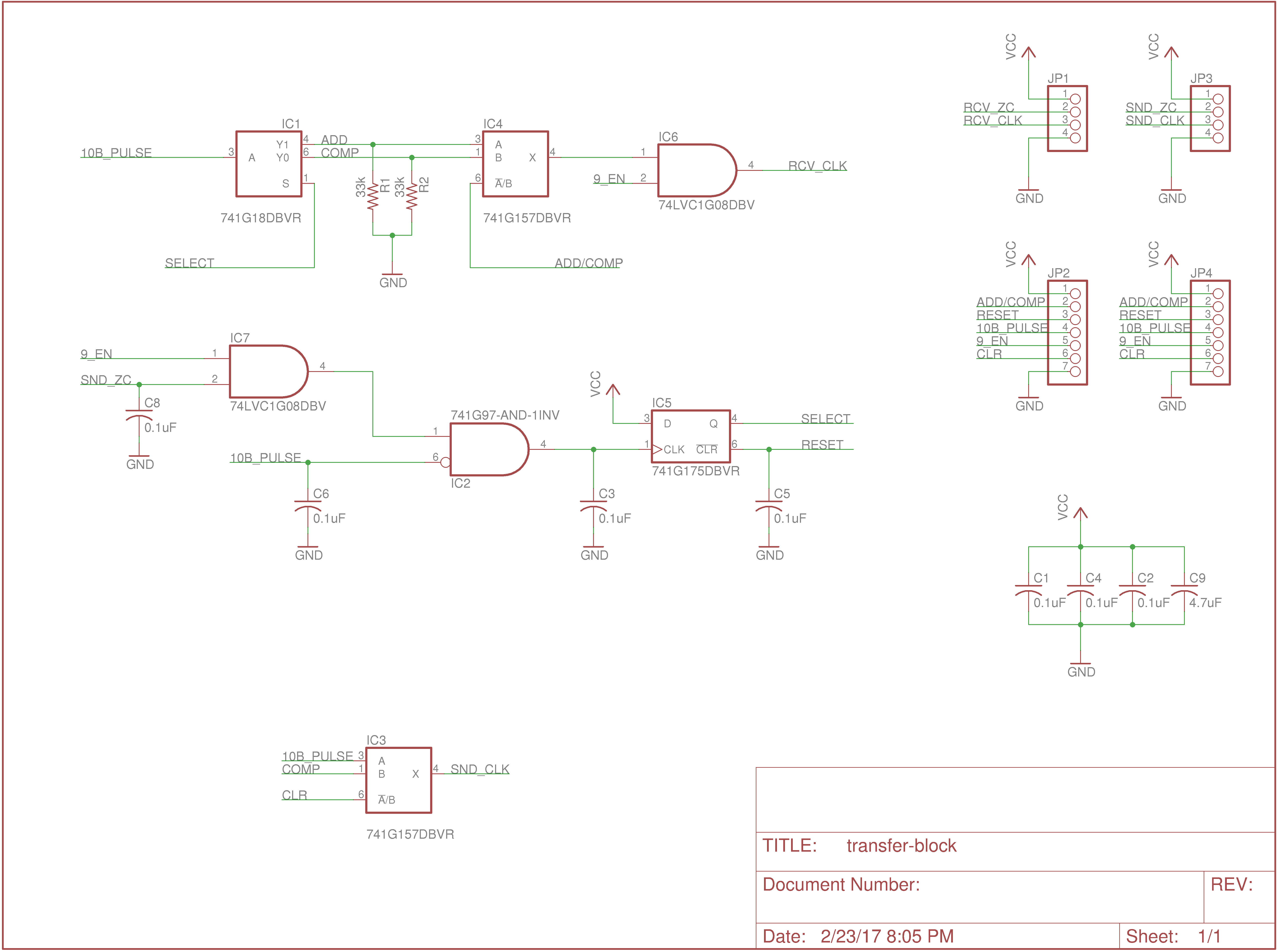
I quickly realized that this diagram from the article was a simplified diagram, and began combing through several pages of schematic. I've slowly identified all the core functionality with this being the resulting schematic (minus the Dekatrons which as done separately):
![]()
-
Lots of Assembly Going On!
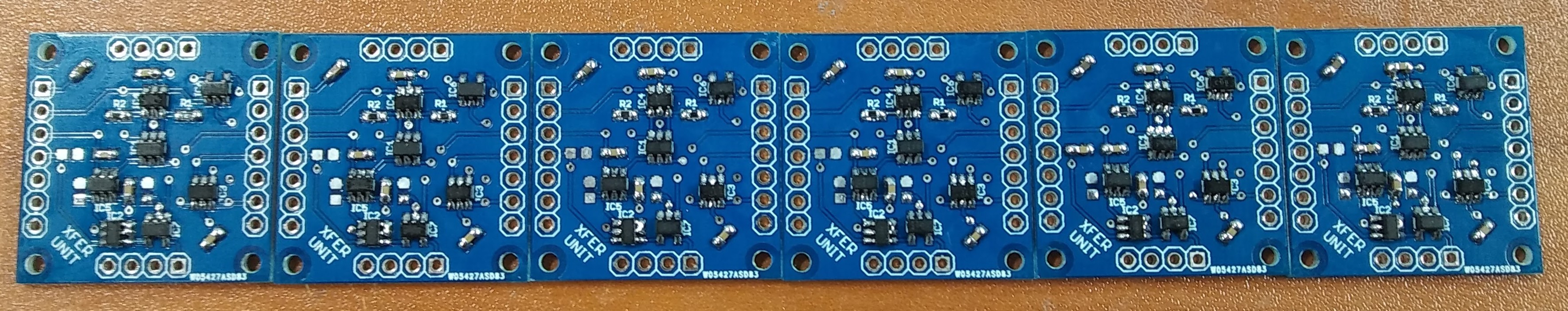
02/23/2017 at 18:56 • 0 commentsFor the next round of testing and debugging, I have a bunch of new modules to build up...
![]()
-
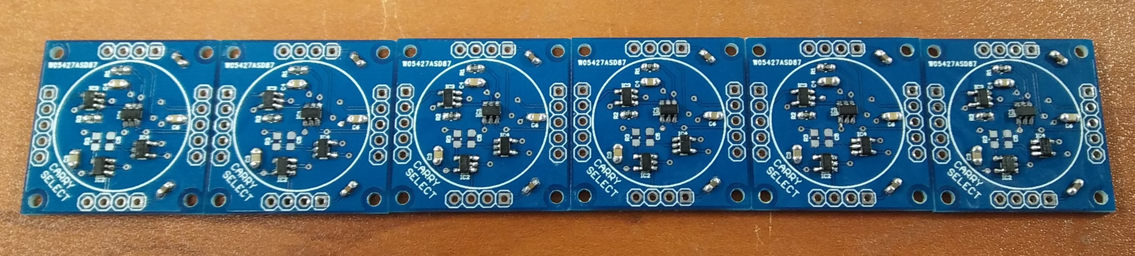
New Carry Select Modules
02/23/2017 at 02:21 • 0 comments![]()
the Carry Select section on a decimal based computer is the section that when when a carry needs to happen, allows for the carry impulse to pass to the receiving location. this "mux" must allow for the initial counting pulse to be selected during a transfer, and then later based on the Carry Block signals to allow the pulses to pass. The OR gate i was using to combine these signals didn't seem to have enough drive strength to properly drive the receiving location logic properly due to the length between them. so on this revision I've added a Schmitt trigger to the design, which seems to solve the issue with both drive strength and line noise.
here is the schematic:
![]()
-
Hackaday at Dallas Maker Space
02/22/2017 at 22:15 • 0 commentsThis time last year I was getting ready for a Hackaday event at the Dallas Maker Space. It was a fantastic event with lots of lighting talks, interesting people, and lots of amazing projects. I did a lighting talk about the WITCH-E project (I wish I could find video of it!), and setup a small table to demo some of the early prototypes. Hackaday's Mike Szczys wrote up a short piece about the project the following week entitled "BOOTSTRAPPED TOOLS, LIVE STOPPED MOTION, AND A DEKATRON COMPUTER"
![]()
-
Recreating Import Documentation
02/22/2017 at 21:54 • 0 commentsDocumentation is King!
One of the first things I started doing as part of the WITCH-E project was collecting documentation. This article from the August 1951 edition of Electronic Engineering magazine provide a fantastic amount of information about the fundamental design of the WITCH, however the text along with the diagrams were in a terrible state. The scans of the document were very low resolution and the text of course was not searchable. Over a period of a year, the text was painstakingly converted into digital text, and a friend (Matt Tuomala) tediously recreated the figures and diagrams. After doing some editing and side-by-side comparisons we had a solid recreation of the original document. This document continues to be a cornerstone of the WITCH-E project and in the new digital format can continue to educate into the future. The original PDF and the new PDF are available via our github project pages or linked below!
Original Article - An Electronic Digital Computer
Recreated Article - An Electronic Digital Computer
![]()
WITCH-E Decimal Based Computer
Document and create a modern replica of the Harwell Dekatron computer known as the WITCH