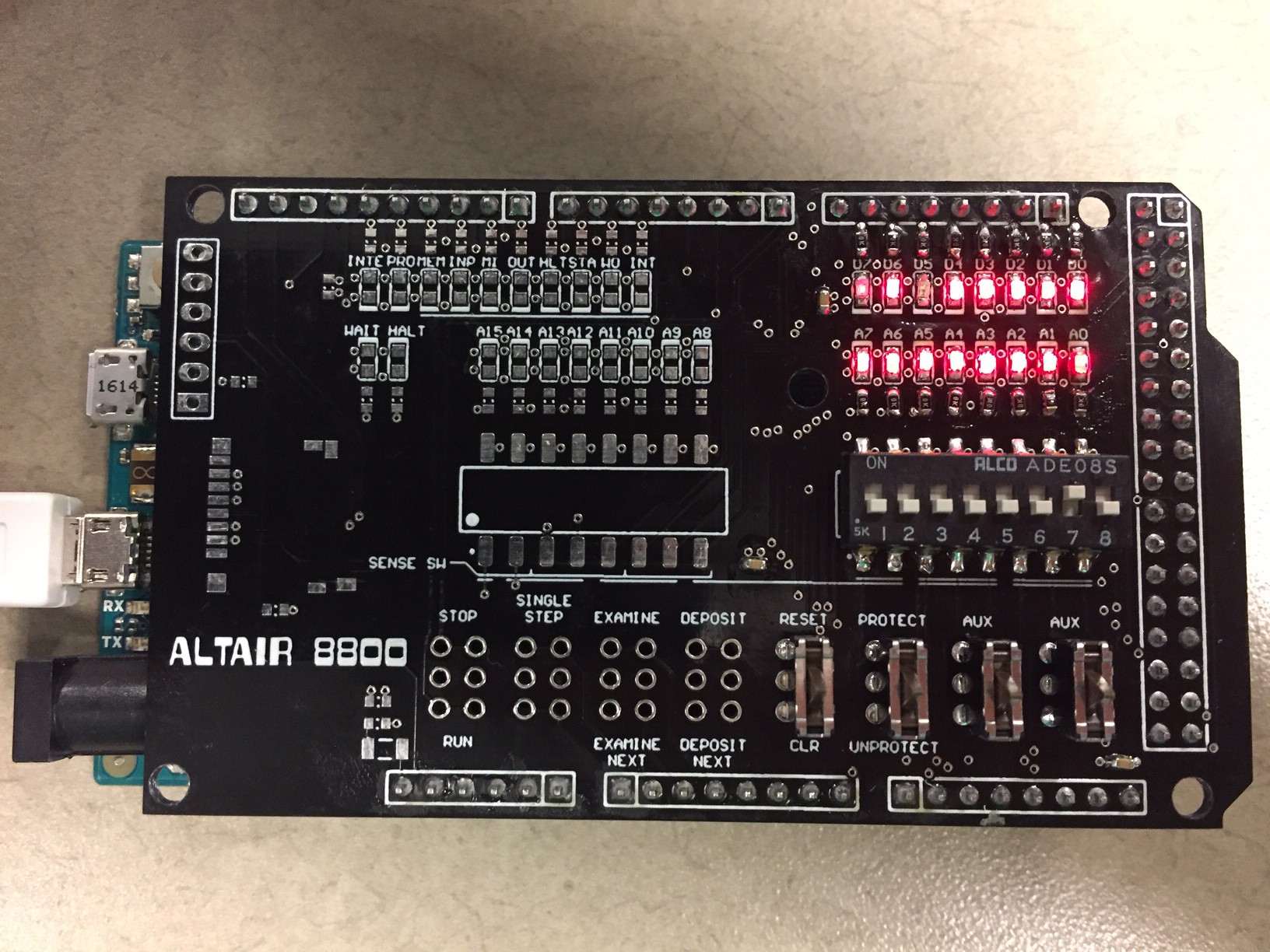
I finished the right side of the board. I checked the DIP switches for polarity, and then soldered the remaining right-side LEDs, resistors, DIP switches, and the four right momentary switches. Since the software has pre-loaded programs, I used those to check everything. For example, setting my DIP switches to 0000 0010 and hitting the AUX1 toggle loads the kill-the-bit program (shown running below). Once I get everything working, I'll put up some videos showing it running.
Next up is left side LEDs,resistors, DIP switches, and the remaining momentary switches. If I get that working, then all my primary goals are achieved. The secondary goals are to get the microSD card reader working, and then maybe the bluetooth module.

Discussions
Become a Hackaday.io Member
Create an account to leave a comment. Already have an account? Log In.
looking awesome!
Are you sure? yes | no