-
LED current
02/28/2017 at 01:53 • 0 commentsI realized I might have a small problem with my LEDs. I started with using the exact reference design, but I'm using different LEDs. I needed to check my maximum current through the LEDs. The reference design recommended 150 Ohm resistors. If I use the 5V supply, that will put 33mA through the LEDs. These LEDs have an absolute maximum of 30mA and a recommeded draw of 20mA. So I have to increase my resistors to 250 Ohms. I don't think I'll change my schematic - I'll just order different resistors. The transistors are rated to 340mA which will be more than enough.
So I realized I need to check another problem. If all LEDs are on, it'll draw 36x20mA or 720mA. I believe this is way more than USB can supply (in addition to the rest of the Arduino). So I will probably have to use an external supply. Since the LEDs are connected to the 5V supply, I also need to check the Due datasheet to make sure the 5V supply can handle at least 720mA. If not, I may have to reduce the current through the LEDs even more. They also may be blindingly bright, so I may have to reduce it anyway. But I'll check a couple before I populate them all.
-
Lights!
02/24/2017 at 18:25 • 0 commentsI originally want to have an LED array like this one:
![]()
I wanted to match the LED with each DIP switch to maintain the same look as the Altair. I was looking for an array of 8 with 0.100'' spacing. Turns out most of these arrays are 10 LEDs wide. Additionally, they are quite large and I need two rows of these. In the end I couldn't find one that was just right.
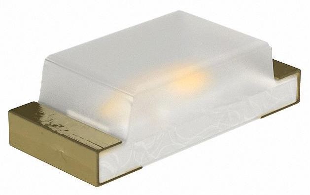
So I decided to use individual surface-mount LEDs. This way I can get two rows and placement exactly in line with the respective switch. It will be a pain to solder all of these and making sure I have them all in the correct orientation. They are in an 0603 package. I will also need a resistor for each of the 36 LEDs. And I found a dual transistor, so only one of those for each pair of LEDs. Still lots of tiny soldering.
![]()
-
Momentary toggle switch
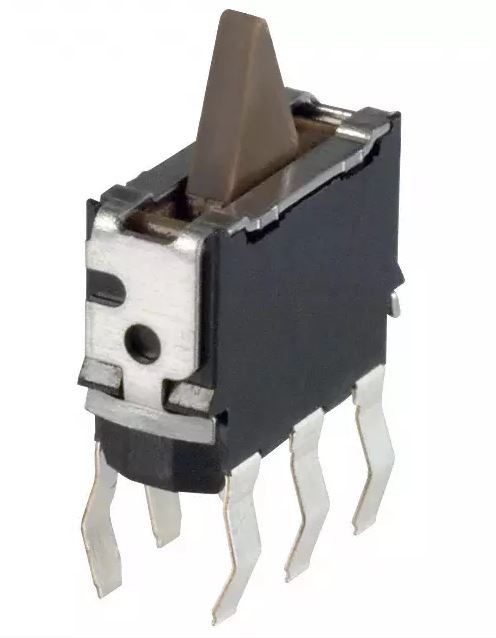
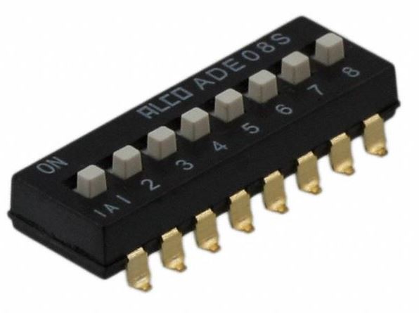
02/24/2017 at 17:48 • 0 commentsOne thing I had to figure out early on was how to do the switches. The switches need to be very small to fit. There are two types of switches - momentary and non-momentary. The non-momentary switches stay where they are when you switch them. These were easy to find - I just used surface-mount DIP switches. They come in sets of 8 which is perfect. The momentary switches were much more difficult to find. They need to be Mom-off-mom style, so they need to return to center after pressing, and they needed to be moved in two directions. This means probably two springs inside them which makes them large. But I found these switches:
![]()
These are Panasonic ESE-24SV3 limit switches. Unfortunately they are through-hole only, but they are the right size. I ordered some to make sure they were return to center and they are. I think I got very lucky in finding these. I'll have to see how well they work in the system. The only other issue is the limit switches are a much higher profile than the DIP switches, so I hope there won't be a problem moving the DIP switches and bump the limit switches.
![]()
-
Software checkout
02/24/2017 at 17:33 • 0 commentsI downloaded the software code from Github to attempt to get the code working on my Due. I ran into a few problems, but was eventually successful. I had never gotten so large of an Arduino project up and running. The first problem I ran across was the missing library I needed to download - DueFlashStorage. But once I got that I was able to compile.
I also ran into a problem getting the code to download to the Due. I don't think it had anything to do with code - I think there's something flakey with the communication to the Due. It often seemed to program, and then fail in verification. So I figured out how to turn on verification, and everything seemed to work ok. There's no apparent error checking other than post-verify which is kind of a problem considering the size of the download.
A second problem I have is a strange 4200 Hz audible squeal coming from the Due. Pressing the reset button a few times and it will eventually go away. I can see this on the scope as a triangle ramp on the 3.3V supply. It also look like an RC curve on the 5V line. There's something broken with the board, but I can't figure out what.
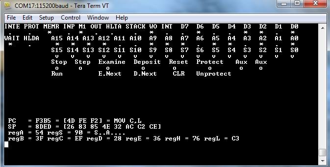
But I was successful in getting the software to display to the terminal. And I could easily emulate button presses with jumper wires to ground. Since I have the software working, I'm fairly confident I can get the project running.
![]()
-
PCB submitted
02/23/2017 at 18:58 • 0 commentsI have submitted my PCB design to the fabricator. I am using EasyEDA which is based in China. I think they offer the best price, but they can take a while to deliver boards since they are coming from far away. They are the same price for 5 as for 10, so I orded 10 boards. This will take quite a bit of time to solder by hand, so I imagine only assembling one.
I chose to go with a black solder-resist layer even if that increased the cost slightly. I am not intending on having a cover, so the look of the PCB is important. I wanted the silkscreen to replicate the front panel look. I took a high-resolution picture of the front panel of the Altair 8800 logo and put that in the silkscreen too.
Altair 8800 front panel Ardiuno shield
A very small fully-functional interface for an Arduino Due emulating an Altair 8800


