 EjaadTech
The Tachometer needed to be small, portable, and should be extensible, so many designs were made and finally the one agreed upon was first tested on a cardboard cutout.
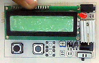
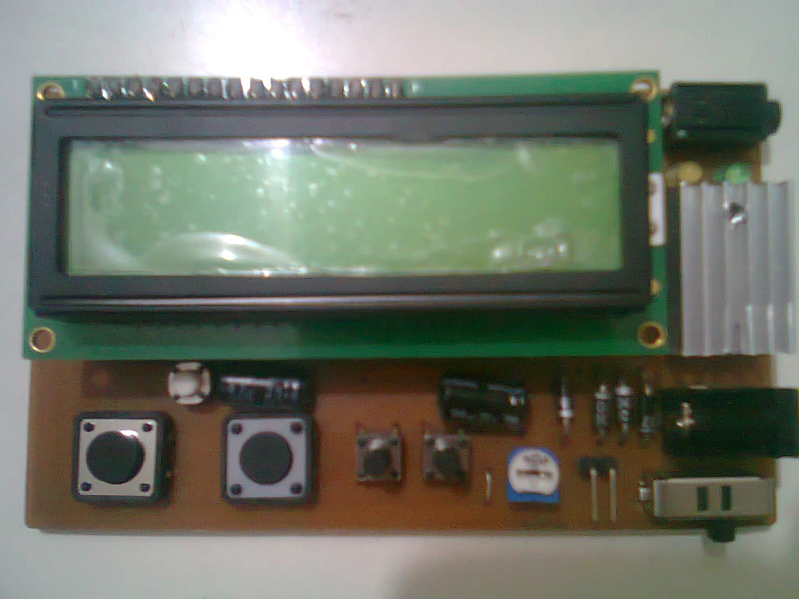
 On top is the ISP connector for programming, on the left are the extra pins left, the sensors input were put with a 3.5mm audio jack female connector and the 2 ICs, the Opamp and the ATMEGA8 were concealed beneath the LCD.
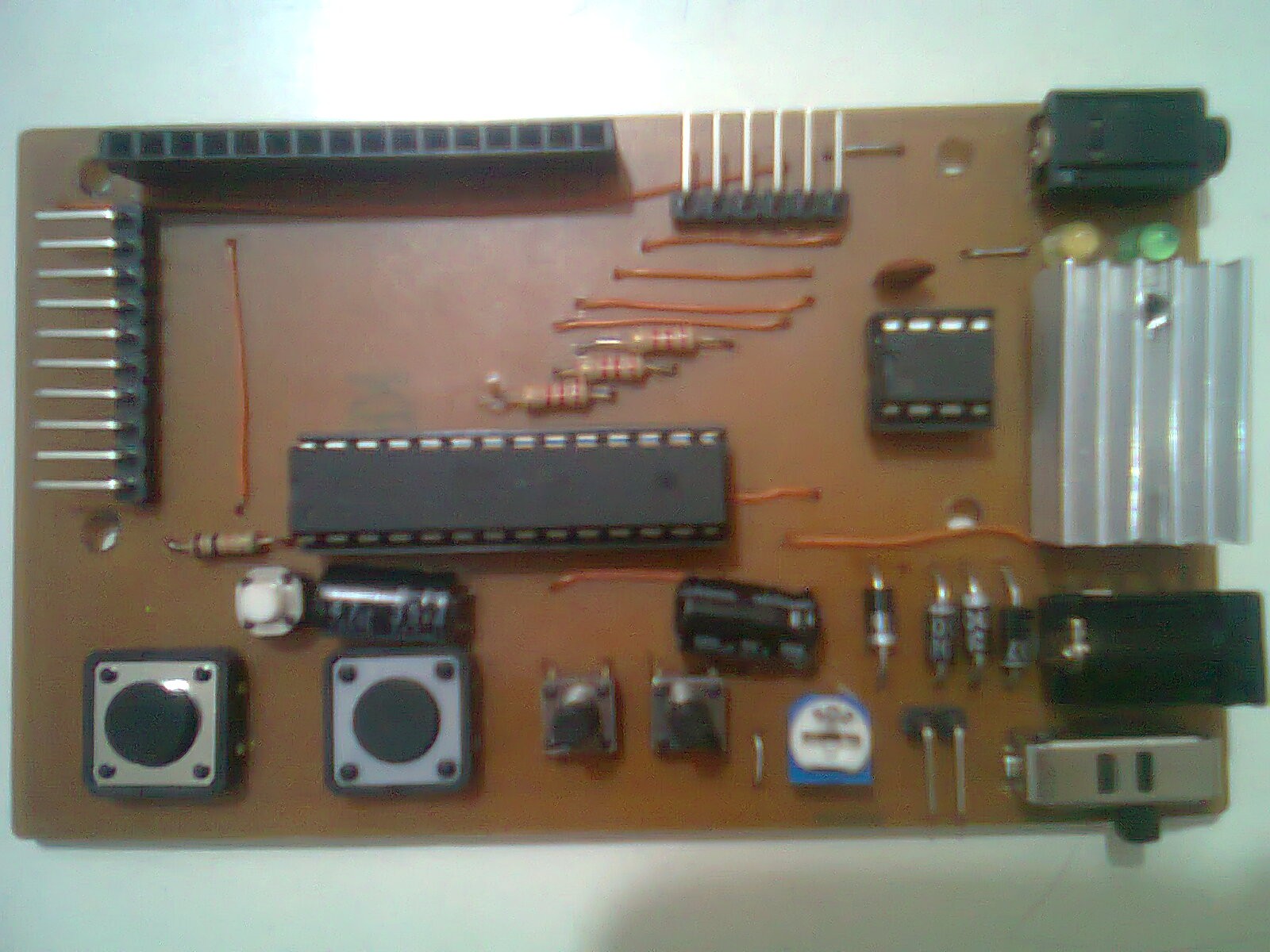
I designed the PCB with big traces and some jumpers as I was just learning to make PCBs back then.. :) the final outcome:
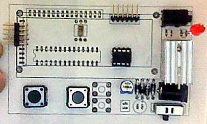
without the LCD
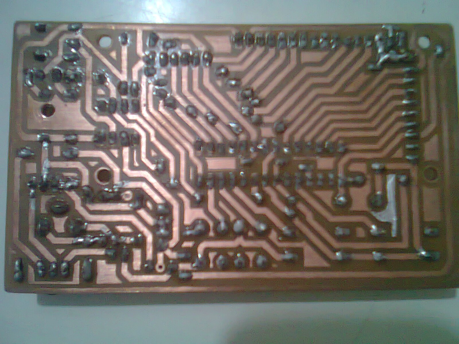
The bottom Copper side
Discussions
Become a Hackaday.io Member
Create an account to leave a comment. Already have an account? Log In.