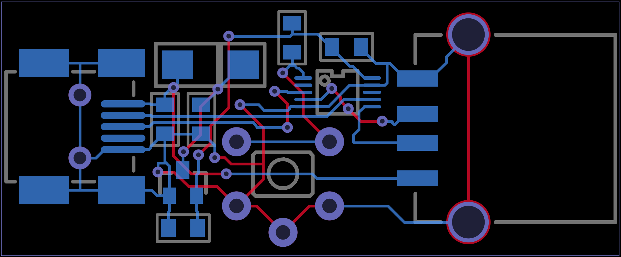
Like pretty much every quick project I make, there's no schematic. I just put the parts into the PCB layout and wire them together. Very quick, but not the best for documentation.
For anyone who wants to see how this board is wired, here's an image showing the routing of both sides.

For anyone who believe this is terrible practice, I'd like to point out nearly all the "open hardware" schematics on the internet are just the parts dropped into a schematic sheet with short wires & net names.
 Paul Stoffregen
Discussions
Become a Hackaday.io Member
Create an account to leave a comment. Already have an account? Log In.