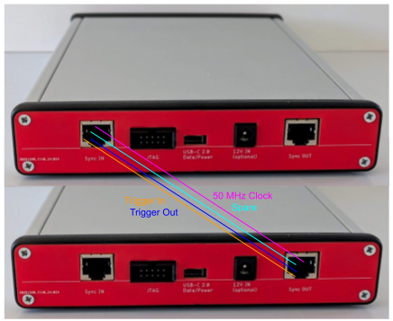
Haasoscopes can be connected together, to either increase the number of channels, or to oversample an analog input to double the sample rate. (We'll have a separate log post about oversampling soon.) The first step in making this possible is to synchronize the clocks between multiple units. This is essential for sampling at the same instant, and also makes it easier to communicate other data between units since inputs can be sampled synchronously on the same clock edges. We'll also need to send trigger signals between units, in both directions, since when either unit triggers we want the other unit(s) to also trigger.

Simple wires won't work because the signals are high speed. The clock we want to send, for instance, is 50 MHz. And the trigger signal edges need to be ~ns risetime with ~ps jitter. We need controlled impedance transmission lines, so we're not broadcasting like a 50 MHz radio station and receiving massive RF interference. We could use coaxial cables, like SMA, but we'd need at least 3 of them. The connectors and cables aren't cheap, they're bulky, and they get messy.
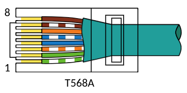
Instead, all these signals are sent over a single Ethernet cable, which offers 4 LVDS pairs and is cheap, ubiquitous, and sturdy. Note, we're not using Ethernet packets or anything at all, just the connectors and the cable. Technically, a standard Ethernet cable is RJ45 jeck with an 8P8C connector, as shown here.

The FPGA on the Haasoscope Pro can easily be programmed to send and receive these LVDS signals as standard IO's. The only extra thing needed is a single 100 Ohm resistor at the receive end of the cable to terminate the signal, which we place on the bottom of the board directly under the FPGA, connected with vias, just like for the termination resistors for the ADC LVDS inputs.
We can connect as many Haasoscope Pro's as we want, by daisy chaining them together, since each Haasoscope Pro has a Sync In and a Sync Out port. We do need to figure out which unit is where in the chain, though. To determine the order, we first find the one unit which has no good clock coming into its Sync In port, by looping through all the connected units and asking each of them if they have a lock on their external clock input. Once we know the first unit, we attempt to find the next one in the chain, the one it's connected to. We make use of the 4th LVDS pair in the cable, the "spare LVDS". We set it high on the output of the first in the chain, then see which of the other units sees a high value on their spare LVDS input. (All other spare LVDS outputs are set low by default.) Once we know the second unit in the chain, we can then find the third in the chain by repeating this trick with spare LVDS signals.
 haas
haas
Discussions
Become a Hackaday.io Member
Create an account to leave a comment. Already have an account? Log In.