 ventosus
We will use linear hall effect sensor from Allegro, specifically, the A1304:
The sensor is fed with Vin=3.3V and outputs quiescent voltage Vq=Vin/2=1.65V when no magnetic field B is present. If we approach with a north polarized magnetic field (B>0), the sensor output voltage Vs will rise towards Vin. If we approach the sensor with a south polarized magnetic field (B<0), the output voltage will decrease towards 0V. The increase and decrease in voltage is linearly dependent on magnetic field strength B and the sensors sensitiviy S. The sensitivity for the A1304 is given by 4mV/G. 1G corresponds to 0.1mT. With an increase of the magnetic field strength (approach of magnet) of 0.1mT thus, the output voltage will rise in 4mV.

In our design, the magnets polarization will be fixed to either north or south facing. We therefore are only interested in one of the polarity ranges. To have a good resolution of the output signal for sampling by the ADC, we thus want to remap the bipolar analog output to a unipolar one. For this we use a simple OpAmp circuitry with an adjustable voltage reference Vr (0-3.3V) and gain A (1-10x).

When Vr is set at 1.65V, both north and south polarized signals would be amplified equally. If the reference is risen towards Vin and amplification doubled (A=2), the origianl north polarized signal range 1.65-3.3V will be mapped to 0-3.3V (Vq now at 0V). If the reference is lowered towards 0V and amplification doubled(A=2), the original south polarized signal range 0-1.65V will be mapped to 0-3.3V (Vq now at 3.3V).
Making the amplification adjustable from 1-10x, we can easily increase the sensitivity of the linear hall effect sensor from 4-40mV/G. This simple circuitry will allow us to experiment with different magnets and expressive button stroke depths to find the ideal combination of signal amplification (A), stroke depth and magnet dimension.
The final output voltage thus will be linear to magnetic field strength. As the magnetic field strength of a permanent magnet does not change linearly with distance, we will need to remap this signal to a linear one in the firmware.
The sources can be found at: https://github.com/OpenMusicKontrollers/space_whistle_button
Here the schematic from KiCAD:

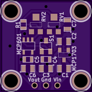
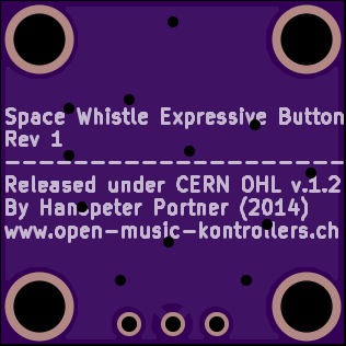
Here the renders from OSHPark:
Discussions
Become a Hackaday.io Member
Create an account to leave a comment. Already have an account? Log In.