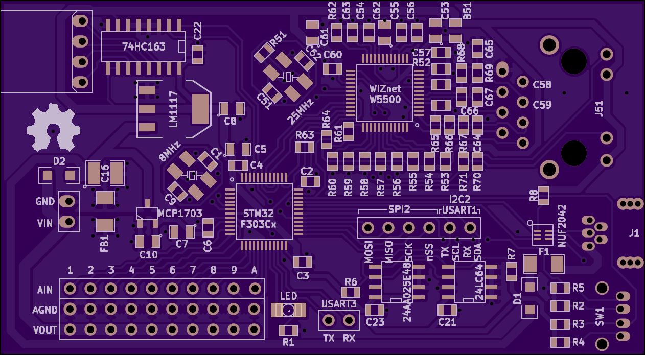
How do we get the analog signals from the respiratory pressure sensor and the 8 expressive buttons via the network to a software synthesizer? We need a MCU and PHY, right? We will use one of our designs we already have at hands from an other project: the 'Chimaera DSP Unit'.
Chimaera DSP Unit
It is a mixed-signal board. It uses a 32bit ARM Cortex M4 microcontroller from STMicroelectronics (STM32F303Cx) clocked at 72MHz. Of the available peripherals, we use the FPU, ADC1, ADC2, ADC3, SPI1, I2C2, DMA1, DMA2, USB, several TIMERS and a couple of GPIOs. The main circuitry runs at 3.3V, driven by a low-drop-out voltage regulator (LM1117).
To leverage the MCU, we use a hardwired UDP/TCP/IP/PHY chip from WIZnet (W5500) which takes care of all the low-level networking and is communicated to via SPI1.
There are two EEPROMS (24LC64, 24AA025E48) which store the MAC address, the configuration and the calibration data of the device.
The analog part of the board consists of 10 analog inputs which provide connection points to connect up to 10 (surprise!) analog sensory peripherals. Those analog inputs go directly to three in parallel running 12bit ADCs embedded on the MCU. In order to reduce noise, The ADC circuitry on the MCU is driven by a dedicated low-drop-out voltage regulator (MCP1703). The sensory units are connected to by 3 wires (Ain, GND, Vout).
Finally there are a RJ45 MagJack and a mini USB socket. USB is solely used to flash the MCU with new firmware. There are also two SPST buttons to reset the board and to get it into flash mode. The board's dimensions are 80x44 mm.
The KiCAD project is located at:
https://github.com/OpenMusicKontrollers/chimaera_dsp_unit
Here a link to the schematics:
Here the renders from OSH Park:


Here the equipped board:

STM32F303Cx and libmaple F3 port
http://www.st.com/web/en/catalog/mmc/FM141/SC1169/SS1576/LN1531
The firmware is developed atop of LeafLabs libmaple.
http://leaflabs.com/docs/libmaple.html
We have ported 'libmaple' to the F3 line of STM32 chips already last year.
https://github.com/ventosus/libmaple/tree/F3
WIZnet W5500
People most probably have come across one of the hardwired UDP/TCP/IPv4 chips from WIZnet, as earlier versions (W5100, W5200) are found on most Ethernet shields for the Arduino and its clones. We use the newest version in the series: the W5500. Compared to its predecessor, the W5200, it gets much less hot and is more DIY friendly, as it comes in a 48-LQFP package instead of a 48-VQFN. It's an easy way to add networking to any MCU project.
http://wizwiki.net/wiki/doku.php?id=products:w5500:start
The chip can be configured with up to 8 individual sockets. In our case the sockets are configured as follows:
| Socket | Protocol(s) | Port | Description |
| 0 | MACRAW/UDP | 68 | IPv4LL (Zeroconf), DHCP client |
| 1 | UDP | 123 | Simple Network Time Protocol (SNTP) |
| 2 | UDP | 319 | Precision Time Protocol (PTPv2 event port) |
| 3 | UDP | 320 | Precision Time Protocol (PTPv2 general port) |
| 4 | UDP/TCP | 3333 | Open Sound Control (OSC) event stream output |
| 5 | UDP/TCP | 4444 | Open Sound Control (OSC) configuration in/out |
| 6 | UDP/TCP | 5555 | Open Sound Control (OSC) debug output |
| 7 | UDP | 5353 | mDNS and DNS-SD (Zeroconf) |
Time synchronization
For an expressive play we need highly resolved data. The higher resolved the data, the higher will be jitter, too. OSC has the advantage, that messages can be timestamped. We use this feature to get rid of network jitter. But in order for timestamping to work, clocks of MCU and host must be synchronized in some way. For this we use the precision time protocol PTPv2 for which there are free implementations for Linux at least. For the other OSs, one can fall back to SNTP, or do without time synchronization altogether.
https://en.wikipedia.org/wiki/Precision_Time_Protocol
http://tools.ietf.org/html/rfc2030
IP
The IP can be configured 1) statically, 2) via IPv4LL or 3) via DHCP. Using the device is thus plug'n'play. A minimal implementation of the Zeroconf stack with IPv4LL, mDNS and DNS-SD makes device discovery by the host straight forward, too.
OSC via UDP/TCP
The device sends its highly resolved continuous event stream via Open Sound Control (OSC) on a dedicated port, either via UDP or TCP.
http://opensoundcontrol.org/spec-1_0
UDP can be a bit faster and may be used on a simple network topology where packets are not likely to be dropped, e.g. direct connection device-host. TCP is to be preferred when packets are likely to be lost (e.g. complex network topology, wireless bridges, www, ...).
The exact OSC serialization format for the event stream will be featured in an upcoming blog post.
Configuration in/out and debug output also is (de)serialized to/from OSC via UDP/TCP on dedicated sockets.
 ventosus
Discussions
Become a Hackaday.io Member
Create an account to leave a comment. Already have an account? Log In.