 ventosus
Before we build all 8 expressive button of the final device, we will do some preliminary experiments with a single standalone unit. In this log entry, we present the component choice for our initial version.
Component choice
We need the expressive button to be responsive and accurate at the same time.
For the accuracy, we thought we would need a heigh enough stroke depth and way of smooth transitioning and theerefore chose a linear ball bearing and cylindrical stainless steel rod. However, the linear ball bearing did not perform as intended, it added a lot of jitter in the movement which was exactly what we wanted to prevent at all costs. We thus converted the linear ball bearing into a sliding bearing, simply by removing the balls. This now works really smooth and as intended.
The responsiveness is achived by sprnig loading the button. The spring parameters were chosen by preliminary tests with a kitchen scale. We thus took our weekest finger (for most people its the smallest one) and sqeeezed the scale with a force that we thought would be still comfortable for prolonged play on the final design. The scale displayed 500g which roughly corresponds to 5N. The stronger the spring, the more responsive the button. But the stronger the spring, the more tiresome it will be to actuate the button, too. A maximal spring force of 5N was a first guess and our initial tests show that it was a good initial guess. The buttons feedback is very prompt.
The lengths of the rod and spring were chosen to have a maximal possible stroke depth of 20mm. The heigher the stroke depth, the easier it will be to tune in to a given position. But the higher the stroke depth, the more impractical the overall play will get, too. 20mm as the maximal stroke depth is a guess what may still be practical. Time will show whether it was a reasonable choice.
At the end of the bolts we will mount the linear hall effect sensor breakout board. The PCBs have not arrived yet, so we can only dry-test the assembly for now.
The Neodymium magnet is just mounted below the collet at the end of the rod. It's exact size will depend on stroke depth and signal amplification. We will know more once have the breakout boards.
Component list
- 1x Slide bearing or linear bearing M4 LM4UU
- 1x Rod M4x50mm DIN 7
- 2x Collet M4 DIN 705 A
- 4x Bolt M3x35mm ISO 7380
- 4x Nut M3 DIN 439
- 1x laser cut acrylic braket with 1x M8 bore, 4x M3 bores (matching the PCB mounting hole spacing)
- 1x laser cut acrylic braket with 1x M6 bore, 4x M3 bored (matching the PCB mounting hole spacing)
- 1x Neodymium cylindrical magnet M8
- 1x compression spring d=0.4mm, D=5,0mm, L=35,8mm, N=14,5, F=5N
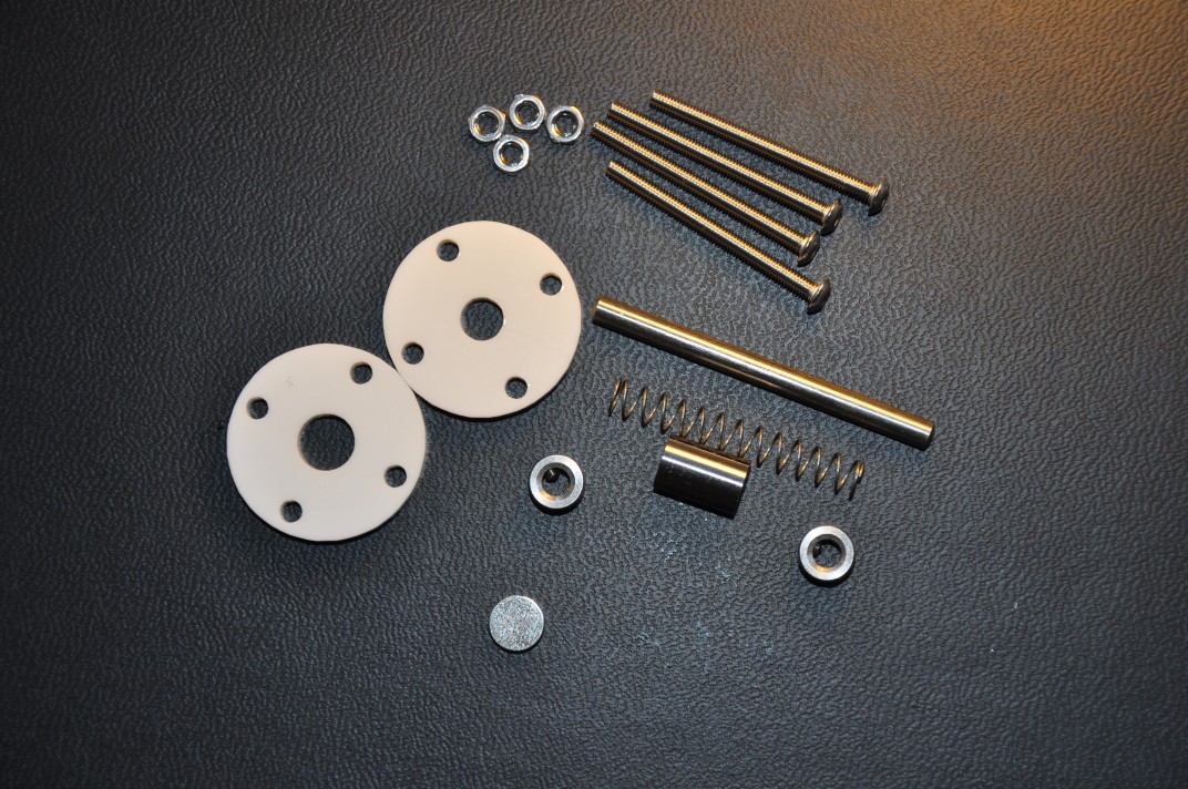
Component images
Parts of a single standalone assembly expressive button.
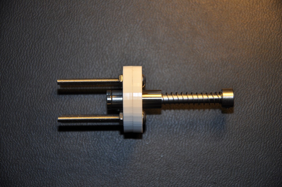
Assembled standalone expressive button:
Animated GIF of an infinite stroke cycle.

Discussions
Become a Hackaday.io Member
Create an account to leave a comment. Already have an account? Log In.