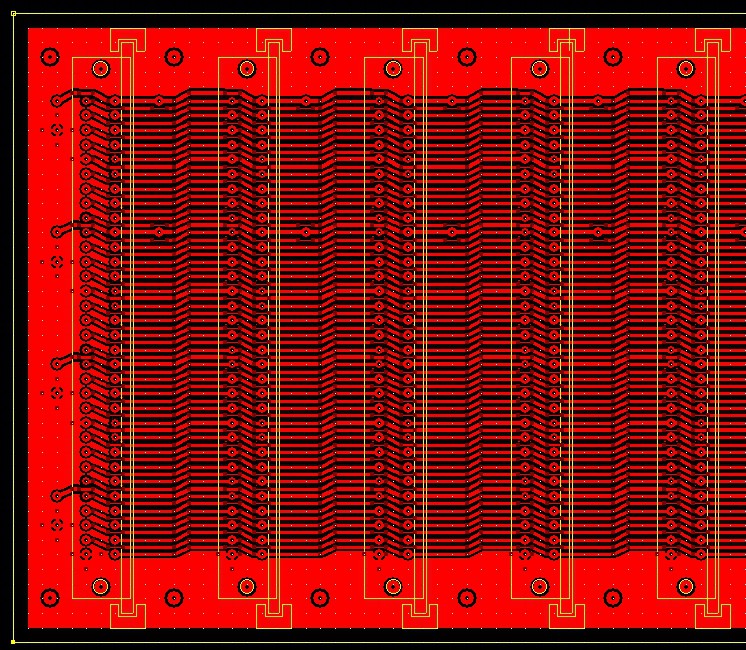
I have been arguing with printers all day trying to print the next version of the back plane -

I discovered that there was problems with the printing more so than the board.
I used an older printed PCB as a reference and I discovered that the 10 mill traces were coming out at 5 mill on the printer.
So instead of WYSIWYG it's more like WYSINWYFG!
After arguing with printer setting for a couple of hours, I gave up and change the size of the traces.
Even then I had to shorten the board as something in the computer (that I can't find - and I was once a CME) is setting the paper size to LETTER instead of A4.
The traces are now 20 and 30 mill and shrink to 10 and 20 mill between pads.
I also dropped the unused middle row of pins in the connectors to give a little more clearance.
It's too late in the day now to go cutting laminate and playing with chemicals so I will get back to this tomorrow some time.
I also got some countersunk rivnuts and they don't work so well without the rivnut tool. The M3 screws strip. I will buy a rivnut tool and that will solve the problem.
I have more or less decided on the Euro Card standard of 160mm x 100mm as I can get that size in my country and I don't need to cut them. The Chinese boards (150mm x 100m) aren't even square and their too thin.
UPDATE!
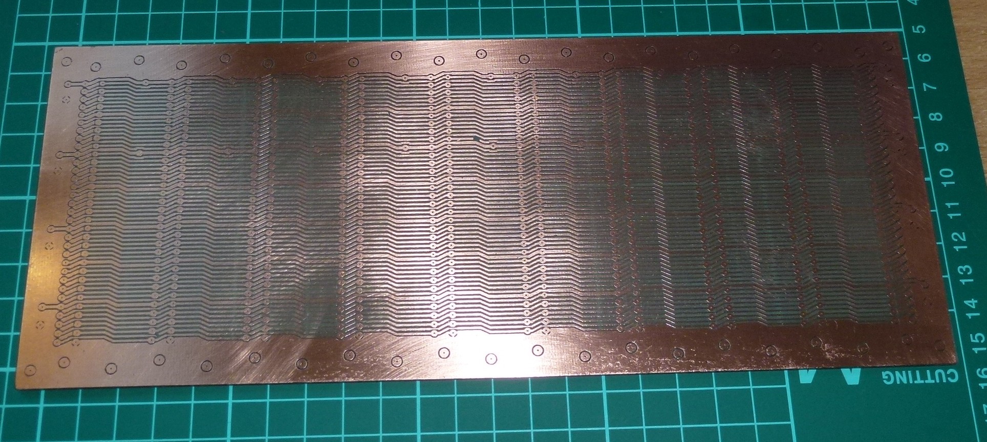
Well, I did another etch.
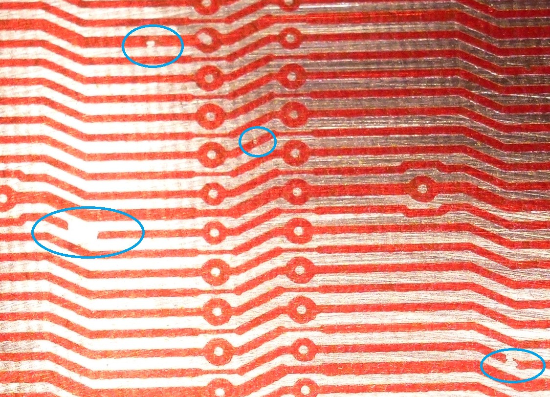
I dropped the laminate during toner transfer ans caused some breaks -

I decided to ignore them and continue as I can fix them with bits of wire and solder. I can *actually* see the traces now. Normally I have to use a Digital camera and zoom it on mt 37" monitor as I have *old* sight now lol.
The Toner Reactive Foil (TRF) creased as it went through the laminator, leaving some gaps due to the creases. It's much easier to examine the green TRF if I use Red toner. This is not critical as the traces are large enough that it *should* work without TRF just how others do plain toner transfer.

I re-did the TRF anyway and you can see from the peeled off sheet that it filled the gaps -

I tried tinning the old board to see how it goes and I decided against it and just used the normal PCB protective coating -

There are 10 x 64 pin sockets so I have at least 640 holes to drill and a bit of patching up a small number of broken tracks.
I am going to try to use strip board as a guide to drill the holes. I will test on the old board first.
By the way, the real small traces ( <5 mill) on the old board were fine! It was just under etched on the sides. I prefer this version anyway because I can *just* see the traces with natural vision.
I will hopefully drill the holes tomorrow. It may be a busy day tomorrow so I will see if I can find the time.
 Hacker404
Discussions
Become a Hackaday.io Member
Create an account to leave a comment. Already have an account? Log In.