 Paul Crouch
I'd read that polycarbonate can be welded with methylene chloride so I bought some (1 litre for less than £10 including the £5 shipping). I tested it on some scraps of polycarb and ABS and can say it solvent-welds polycarbonate and ABS extremely well. In the photo below, the top two pieces are well-and-truly fused and will not peel apart and the bottom piece, that was bonded to a failed ABS print, still has the skin of the print on it after some not-inconsiderable force was used to separate them.
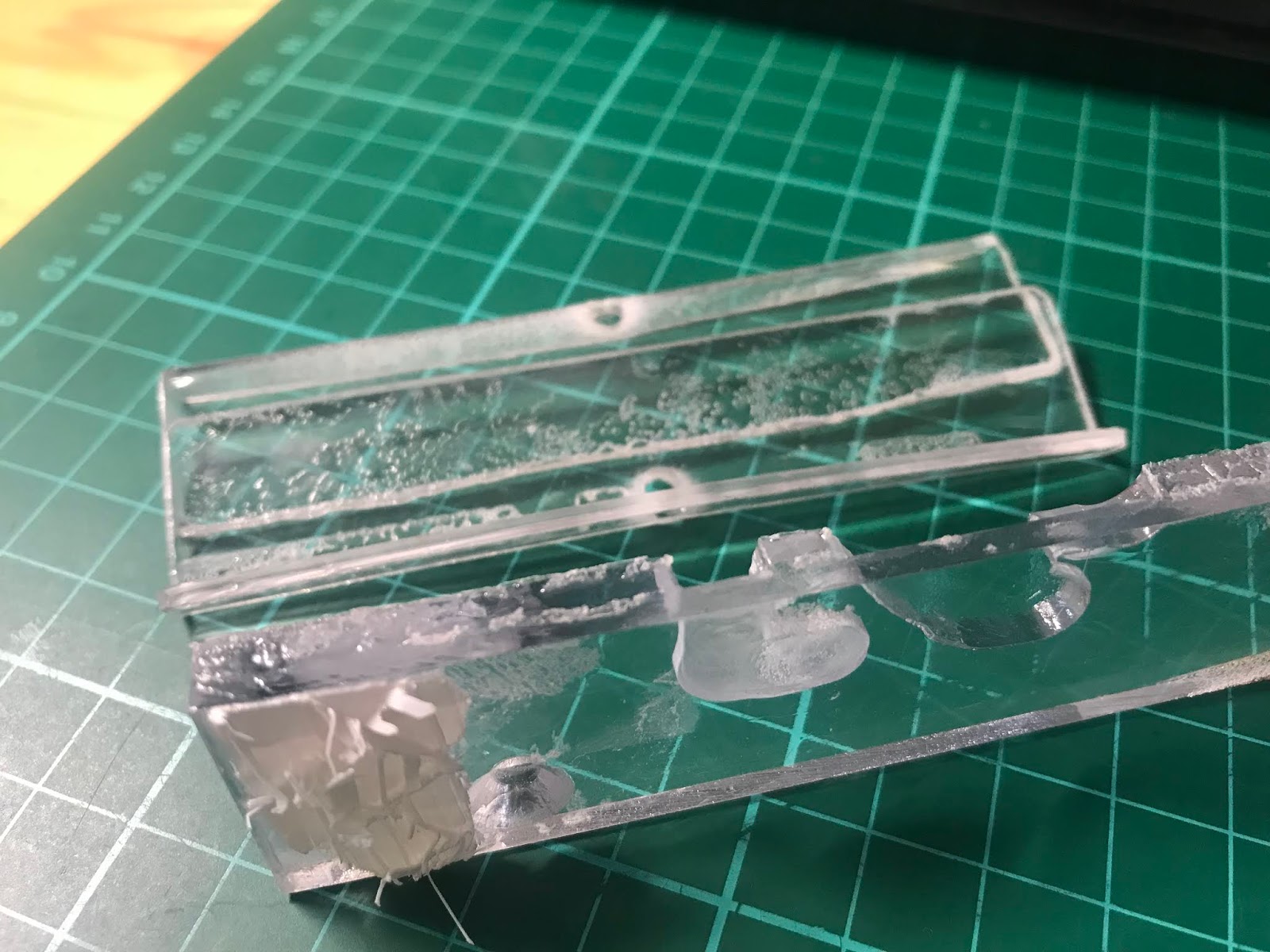 |
| Solvent-weld polycarbonate and ABS with methylene chloride. |
Just to check; acetone barely touches polycarbonate and though it does fog it slightly it then fades. The polycarbonate strip in the photo below was dipped for a few seconds in each chemical. I would say methylene chloride is better than acetone for ABS too, certainly faster, though harder to spell :-)
 |
| Acetone dip on top, methylene chloride on bottom. |
Assembly
I did a dry-fit of the parts and checked for any show-stoppers. I didn't want to ruin the material. It's not hugely expensive but it's not zero cost either and would take another week to come through.
 |
| Dry-fit. |
The image below shows my intended plan. The main reasons for the overly complicated layering are because I didn't want the LED strip to sit proud of the main skin and I'd had an internal dimension to match for mounting.
 |
| The plan. |
I just had to hope I'd not ruined the plastic after attempting to solvent-weld the camera shield and cap with a less-than-steady hand. Annoyingly I managed to scuff the polycarb too. As advised, I left it overnight to fully set.
 |
| Letting it go off over night. |
It's far from flawless, but it fits and I'm making progress! In my eagerness, I didn't take any photos of the spacer strip being bonded. I used four clamps (in the photo above) to clamp the spacer strip after I'd applied the methylene chloride with a small paint brush, then I brought the "oldest" clamp to the newest position, working my way around. If you don't look too closely it looks fine. It's a first for me so shouldn't beat myself up over it.
 |
| Test fit for size. |
Before I mounted the RGB LED strip I again did a test-fit. The wire termination end has heat-shrink tubing on it that I cut off so it wouldn't restrict the wire routing. I'll have to re-insulate it somehow. To my surprise there was another LED under the heatshrink. I hadn't given it much thought, how else would they do it? They're not going to remove one, that's not cost effective. Just struck me as odd.
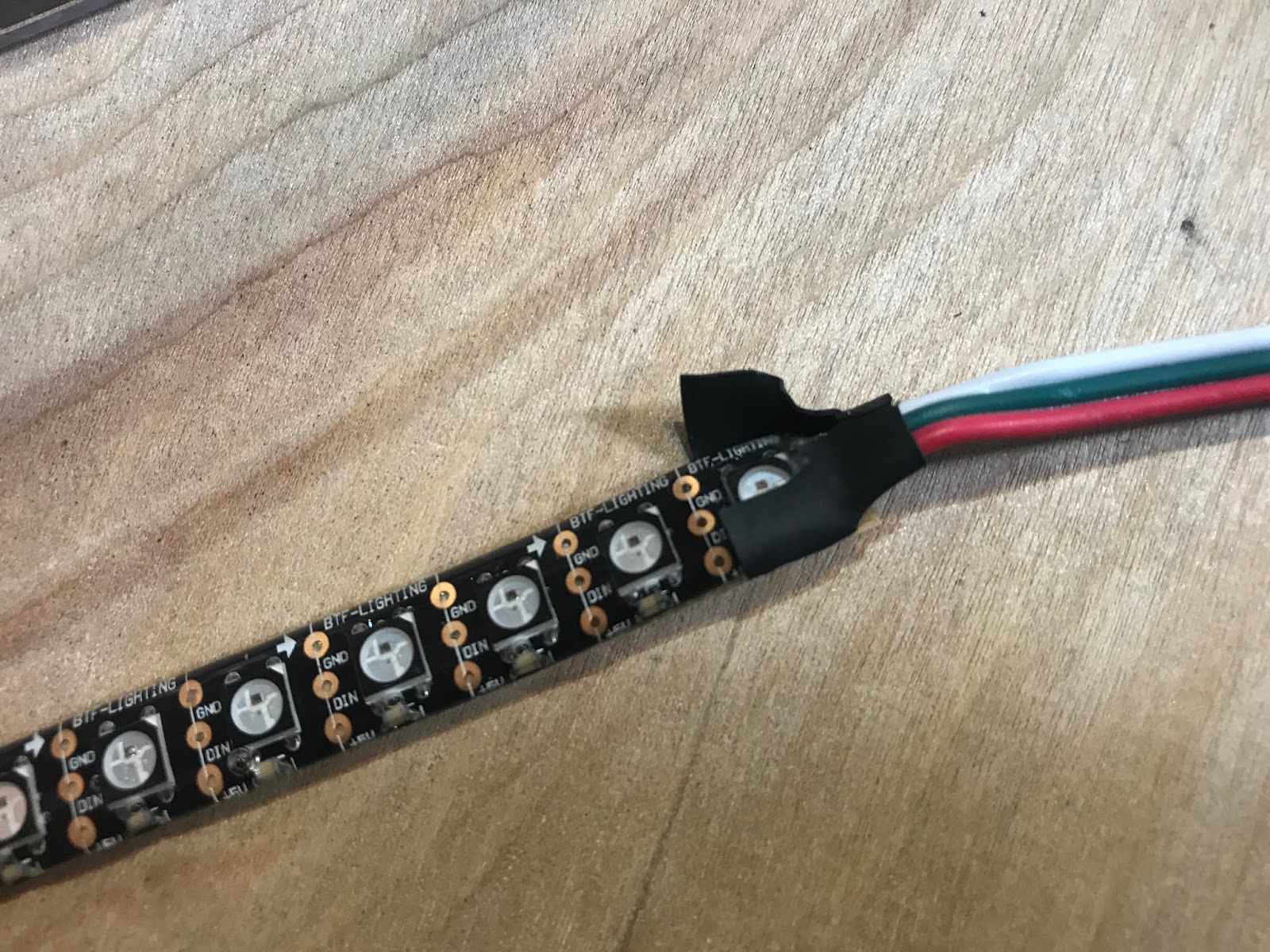 |
| First LED is covered up. Common practice? |
With the LEDs stuck on, I clamped the strip of polycarb (that will become the sensor collar) in place to get a feel for how it will look. The white protective film is a close match for the white that it will eventually be painted. I'll need to mask and paint the dodgy-looking welded areas too.
 |
| Mock-up of sensor collar. |
Now I need to work out exactly what sensors I'm placing and where. Back to the CAD...
Discussions
Become a Hackaday.io Member
Create an account to leave a comment. Already have an account? Log In.