Well, my cunning plan for load-bearing mounts seemed to like too much hard work. Instead I used M6 rivnuts on the bulkhead and strategically placed hex-socket pan-head bolts through the sensor-ring (base of head/camera shield) to secure the two together.
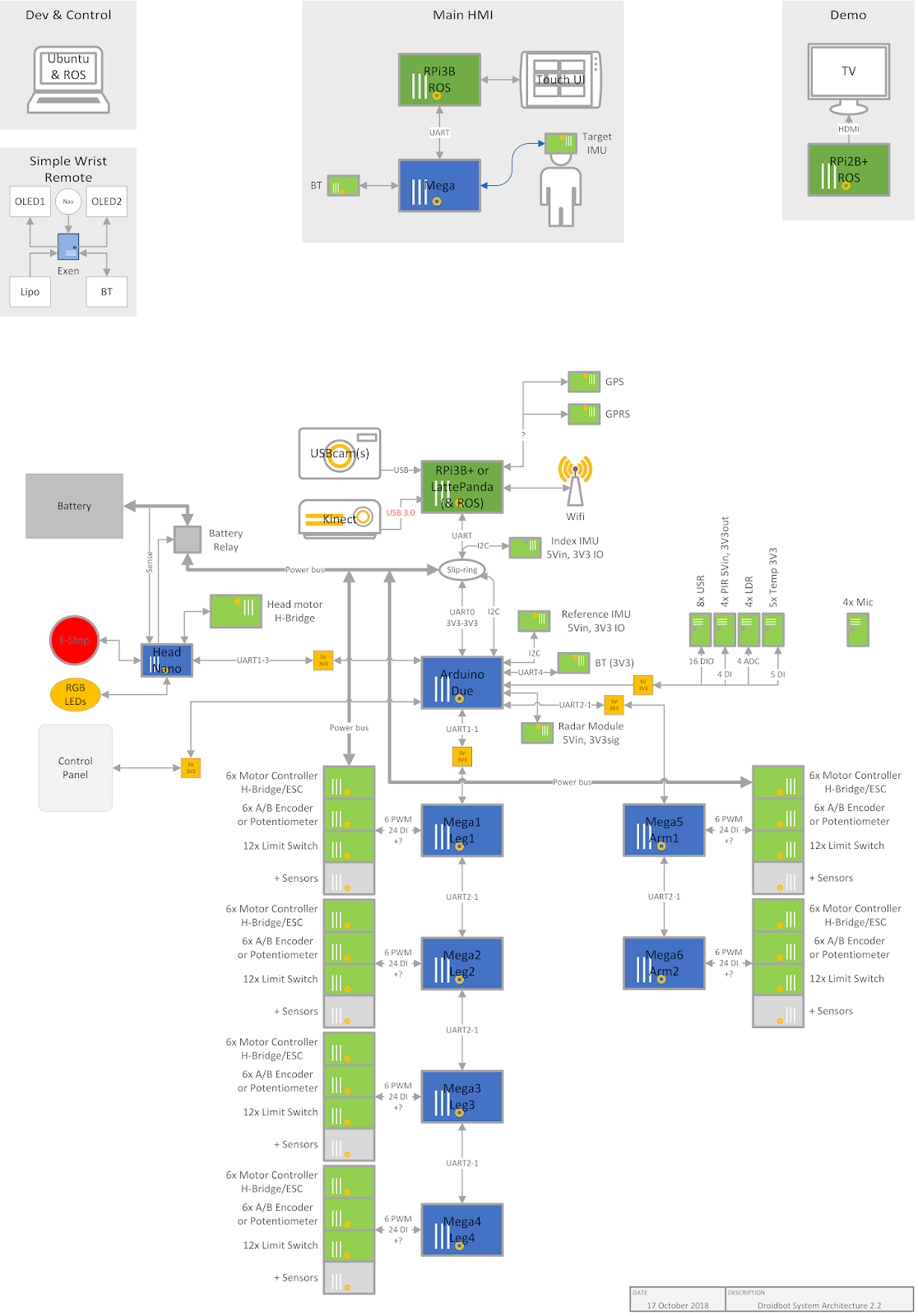
With the head removed again, I mounted the sensors and began to consider how best to wire them back to whichever processor I was going to use. It got me thinking a bit more about the system architecture overall; what did I plan to use where and how was it going to inter-connect? I scribbled several diagrams on paper before moving to the digital domain. Below is the latest iteration of my imagined system architecture for Droidbot. It is an incomplete overview only, something to help me avoid major snags.
 |
With the larger system in mind I dug out my Raspberry Pi (2, I think) to get a better understanding of how it all works. I quickly concluded I should get the latest and greatest RPi3B+ if I wanted to do image processing and similar, so I ordered one.
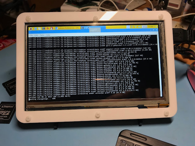
7" 1200x600 touch-screen for RPi
While waiting for the 3B+ to come in, I again connected up the display I had bought (some time ago). It's a reasonably sized 7" HDMI display with a touch panel, it's very nice and works well.
 |
As part of the UI, further down the line, I'd like to have a remote touch-screen GUI at the operator's station. This panel is intended for that and it seemed like it would be up to the task with the right hardware and software behind it.
Playing with the RPi led to a whole load of RPi/Linux/ROS fun...
 Paul Crouch
Discussions
Become a Hackaday.io Member
Create an account to leave a comment. Already have an account? Log In.