 Paul Crouch
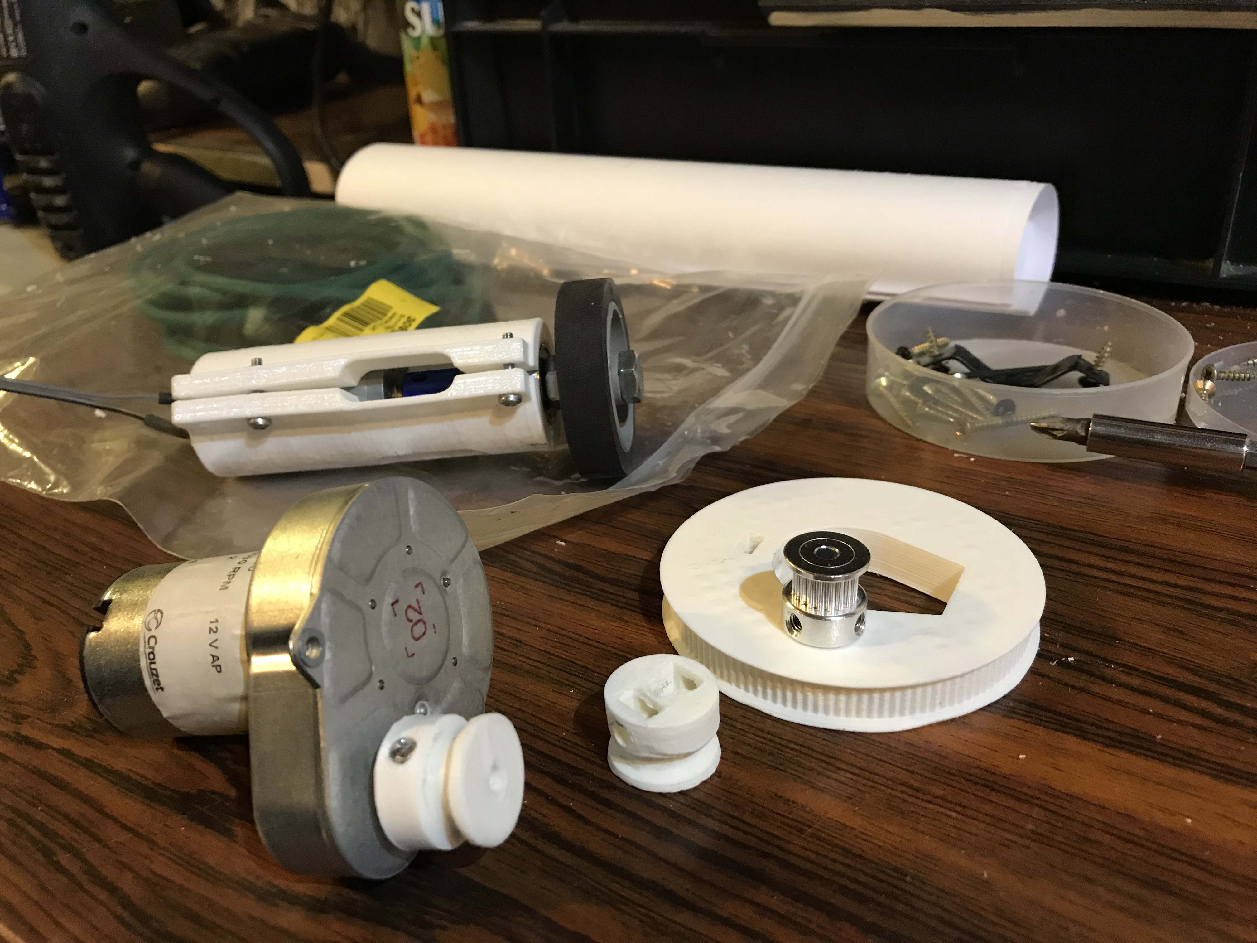
I had to strip the whole thing down to cut additional access holes in the chassis so I could reach inside to mount the GT2 belt on the pulley. After re-assembling and touching up the paint, I set about re-motorising the head. I was using a length of open GT2 belt rather than the closed-loop type, because it's what I had available. Unfortunately the necessary tension needed to avoid belt skipping was too much for my DIY joint and the belt kept breaking. I reprinted the pulleys but for 5mm round belt (I have some for my mini lathe) and that set-up almost worked but I couldn't easily get enough tension for the not inconsiderable weight and drag of the bearing and assembly. Time for Plan C: a bodged variant of the original direct-drive but with a smaller drive wheel and rigid mounting.
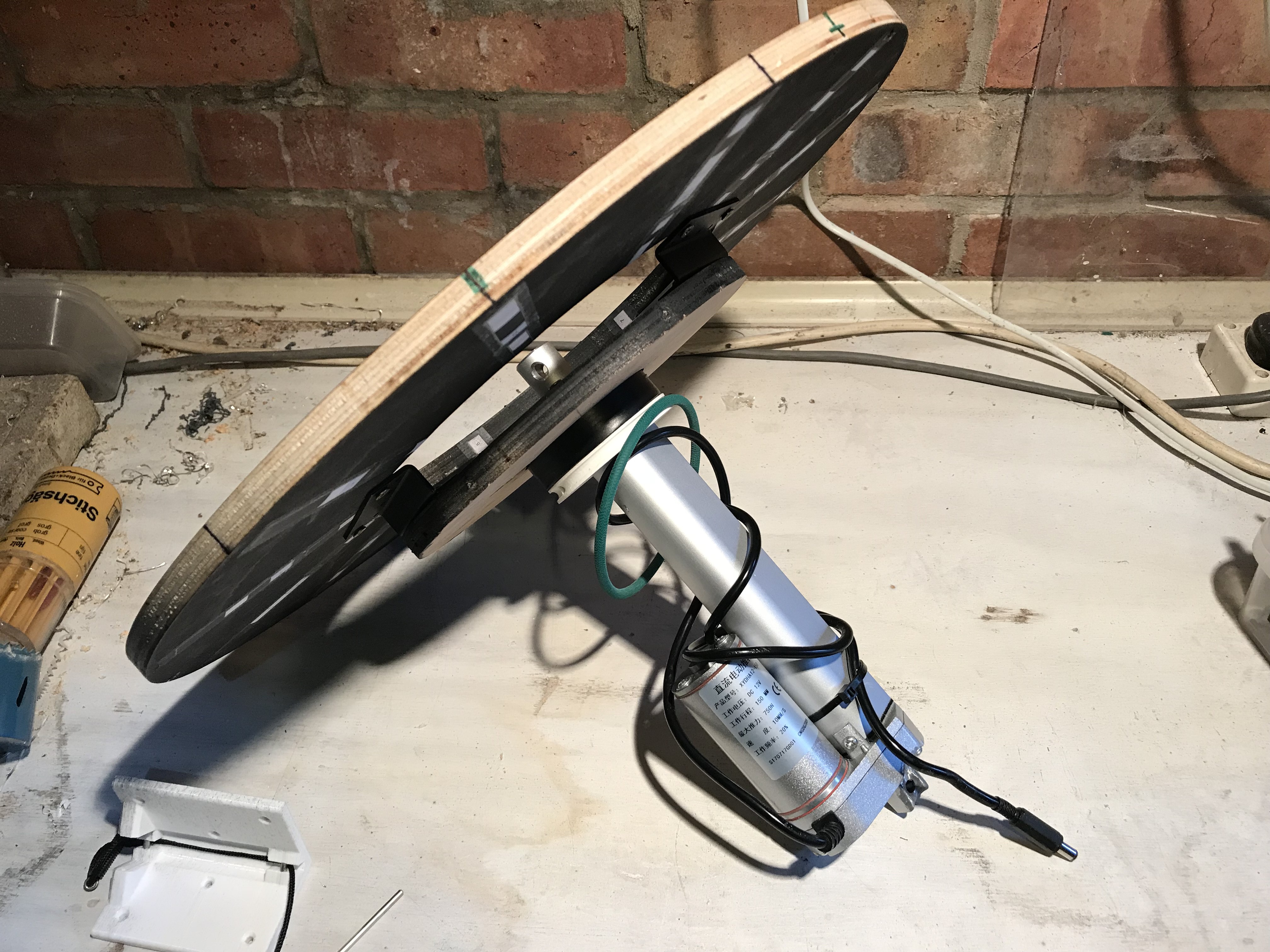
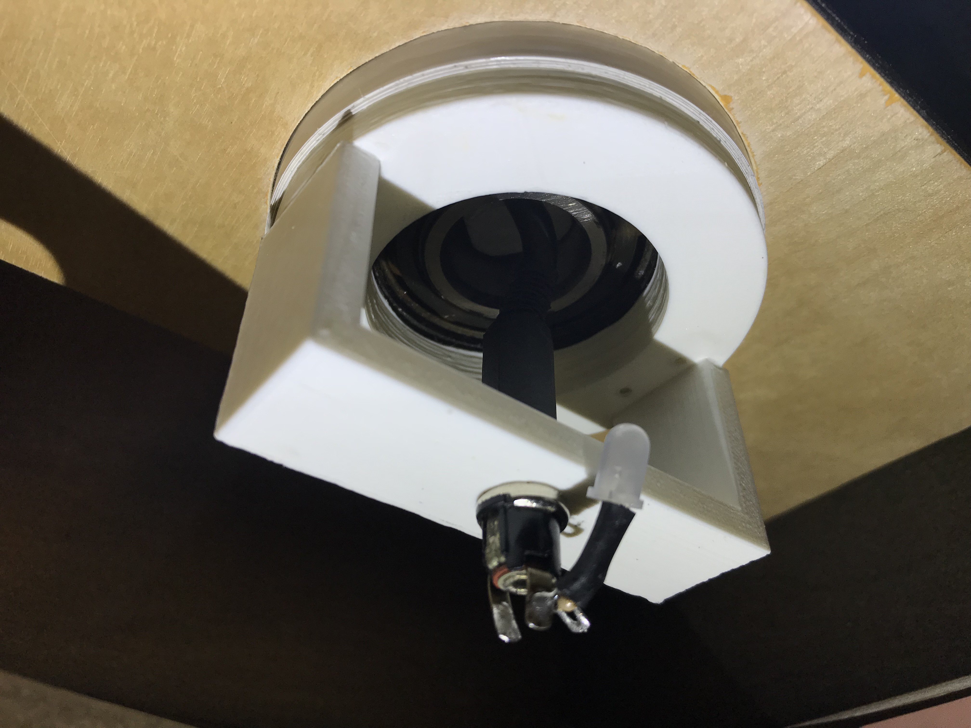
I also abandoned trying to use the small bearings to maintain electrical continuity for the head lift motor (linear actuator) and resorted back to a mini-DC barrel plug and socket mounted in a bridge under the bottom bearing. The static contact resistance of the bearings were a few hundred Ohms and varied wildly when turned. The bearings were only cheap Chinese ones though, better quality bearings may perform better. The DC jack resistance was a lot lower and more consistent and seems to work perfectly, for now at least.
Video!
I'm also trying out some new video editing software... and maybe I should get a microphone too.
Discussions
Become a Hackaday.io Member
Create an account to leave a comment. Already have an account? Log In.