 |
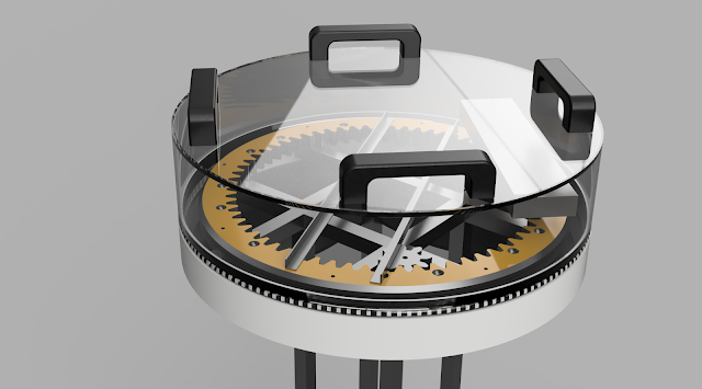
| Render of head CAD model. |
I've purchased the necessary polycarbonate for the protective camera shield and sensor mount, though I've not had chance to assemble it. I intend to use a Microsoft Kinect 2 depth camera (for point-cloud in ROS) and a stereoscopic camera for tele-presence operation, both mounted on the ring. I have the Kinect but I'm undecided on how to do the 3D imaging. To begin with, I'll be starting with a regular camera mounted on simple pitch-roll mechanism (yaw and active camera swapping taken care of by the ring). I have purchased a Logitech C920 for development purposes as it provides HD quality images with auto-focus and comes with stereo microphones (may help get started with remote sound location, though it'll probably be limited as the camera will be behind the polycarbonate shield).
 |
| Testing the RGB LEDs |
A water-resistant RGB LED strip (100 per meter) will provide short-range illumination for the cameras in addition to simple communication (of sorts) to anyone nearby. The LEDs will be recessed around the head, below the camera shield, above the sensor ring (the white strip in image above).
I printed the ring-gear segments in ABS and solvent welded them together with acetone. The ring was then screwed down through holes drilled in the lazy-susan bearing. A 3DP 8T pinion gear mounts to the gearhead motor to drive the 64T ring-gear. Yes, it hurts if you absentmindedly trap a finger in there.
Aluminium angle and 6mm polycarbonate (I used what I had handy) form the bridge which carries some electronics and a slip-ring. A small polycarbonate deck spans the width of the bridge above the slip-ring to keep an IMU (MPU6050) centered. The IMU will be used to keep the robot level and balanced. The electronics may be re-housed in waterproof enclosures if I ever get this thing mobile.
I had an IR photo-reflective sensor counting teeth and a magnet operating a reed switch to detect the home position but I was unhappy with the performance. The resolution of the 64-tooth ring-gear and sensing method wasn't giving the results I wanted so I swapped in a 600-tick rotary encoder on a second 8T pinion.
PID
My DIY PID position control code was then giving reasonable results but I knew it should be capable of better. I've long known the concept of PID control but there's nothing like getting your hands dirty to really drive it home. Below is one of the many plots I made when trying to tune the PID values.
| My DIY PID code wasn't too bad for a first attempt. |
I'd type in a target position on a serial terminal and for most positions, most of the time, the head would turn reasonably enough, but still it could be better. Too much hunting that was hard to reduce without increasing the time to target.
The results I was seeing suggested my proportional calculations were suspect. I couldn't see how the relatively simple code wasn't functioning but I also admit I'm not an expert. Time to try known-good code so I swapped to the Arduino PID library and started the whole tuning thing again. You can spend the rest of your life tweaking PID values; constantly trying to get slightly better performance under slightly different conditions. I need to draw a line under this. Find values that are good enough and move on. However, before I can do that, I need to fix the CW/CCW behaviour that I broke in the PID swap.
Ultimately the target won't be set by a step-change entry on a serial terminal but by a more fluid parameter coming from the head-tracker or another algorithm and that's not helping with the PID tuning. I need a more analogue way of setting the target position. I considered a 360° pot or rotary encoder but that would mean more work in the wrong direction. I need IMU data here so I should use an IMU, but can't use the one mounted on the bridge, it needs to remote.
IMU & BT
I've just got done testing IMU data transmission via Bluetooth HC-05 modules. The IMU will be mounted on a lightweight helmet worn the operator to track head movements. The helmet provides convenient mounts for sensors, processors and battery.
 |
| Testing BT link. |
Next I need to format the data to make it easier to extract and feed in as the target position (0-360°). The X and Y values will control the pitch and roll of the camera mount, eventually.
Then...
Then I can fix the CW/CCW behaviour of the head and perform final tuning on the PID allowing me to make the head shield and mount the sensors. I'll probably have a stab at the legs then.
 Paul Crouch
Discussions
Become a Hackaday.io Member
Create an account to leave a comment. Already have an account? Log In.