 AltMarcxs
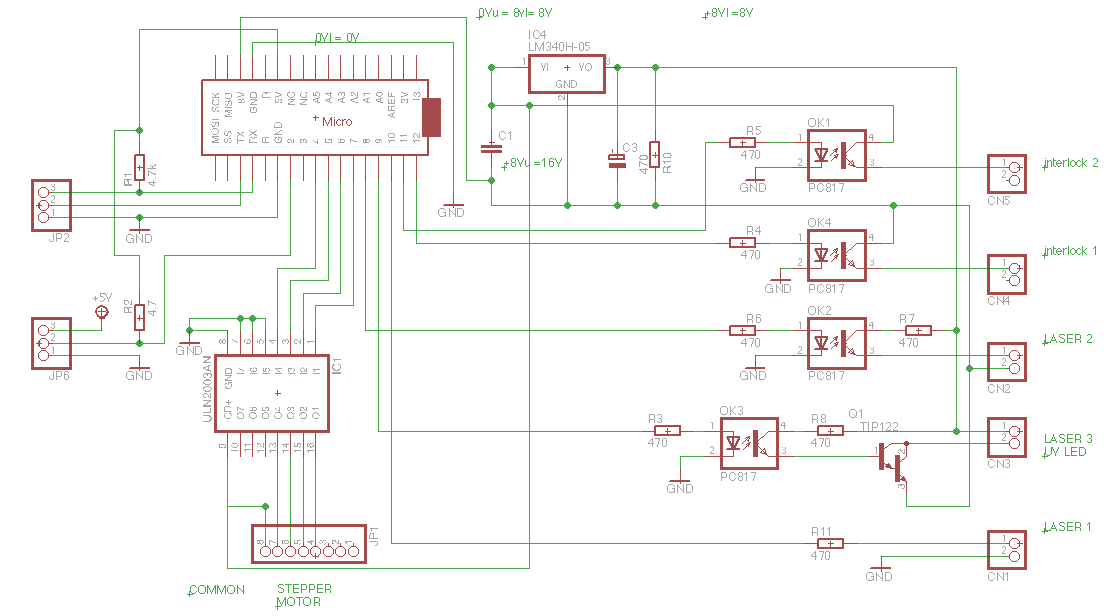
This board drives the laser drivers (Flexmod P3), the stepper motor which turn the assembly and additional 5V output used to switch on/off the UV laser mounted aside of the assembly ( will be used to expose PCB traces to UV ).
It's receiving it's data, the values of laser power and an angle value to move the stepper, from the coordinate board with the Teensy 3.1 on it.
It's also take care for E-Stop and Interlock.
It contains some opto isolator because each laser driver get it's own 8.5V (at 2.4A) but the stepper motor need more the 8.5V, bridging them and he get's 17V.
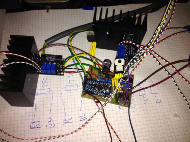
And it does work.
Discussions
Become a Hackaday.io Member
Create an account to leave a comment. Already have an account? Log In.