 CentyLab
Purchase from Tindie (USA) and Lectronz (Europe)
Status: We now can ship directly from the US.
Project Status
We got the board working on ESP32 and STM32 via Arduino Lib. We will soon release PicoSDK for RP2040 if you would like to work natively on C++.
Featured in GreatScott!
Libraries
- AP33772S Arduino - GitHub
- AP33772S RP2040 Cpp - GitHub
- AP33772S PicoSDK - GitHub
- AP33772S CircuitPython - GitHub -> Thanks to hansendc
- RotoPD Hardware - GitHub
Description
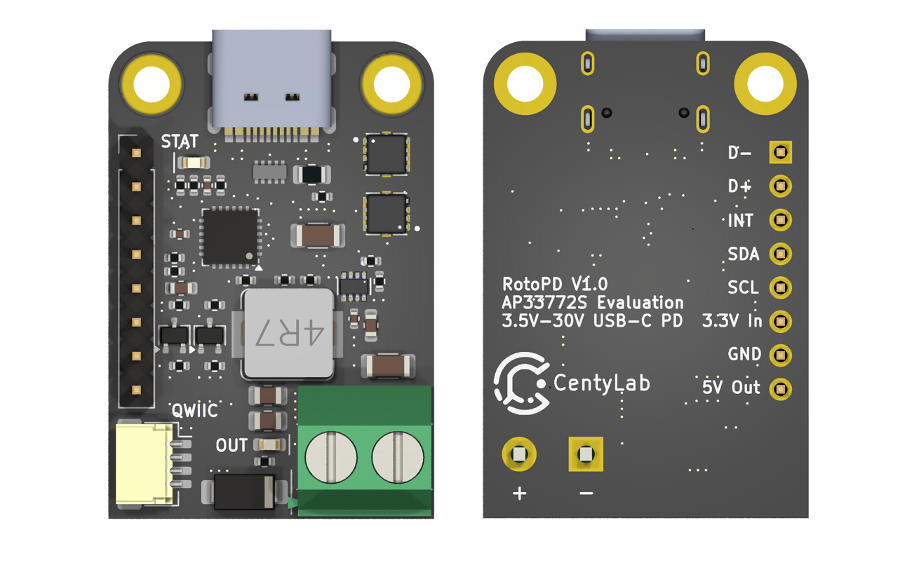
While traditional power adapters can provide a variety of current but fixed to 5V output, our RotoPD leverages advanced power delivery protocols to achieve a versatile output range— 3.5V to 30V at 150W max. The breakout board use a stand alone Power Delivery Sink controller to negotiate with your modern charger and provide different output voltage.
Centylab's RotoPD can unlock more advance mode in your USB-C power supplies like Programmable Power Supply (PPS) and Adjustable Voltage Supply (AVS), to provide even more granular voltage adjustment. The RotoPD simplifies power negotiation with USB-C adapters, handling the complex process of establishing power delivery contracts. The controller does all the heavy lifting of power negotiation and provides an easy way to configure over I2C, free your micro-controller from the complicated USB-C PD protocol.
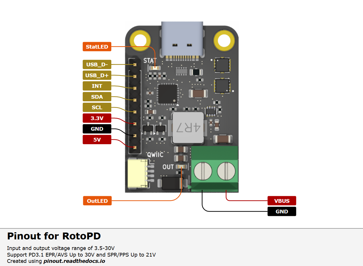
To config the board, you will need an I2C bus. The board integrates seamlessly into the Qwiic and STEMMA QT ecosystems, no soldering is required. We also include an logic level shifter on board to work with 3.3V or 5V I2C system.
To make it even easier to use, RotoPD includes a built-in buck converter that efficiently steps down USB-C VBUS power to a stable 5V 2A output, making it perfect for powering microcontrollers, sensors, and other low-voltage components in your project.
Technical specification
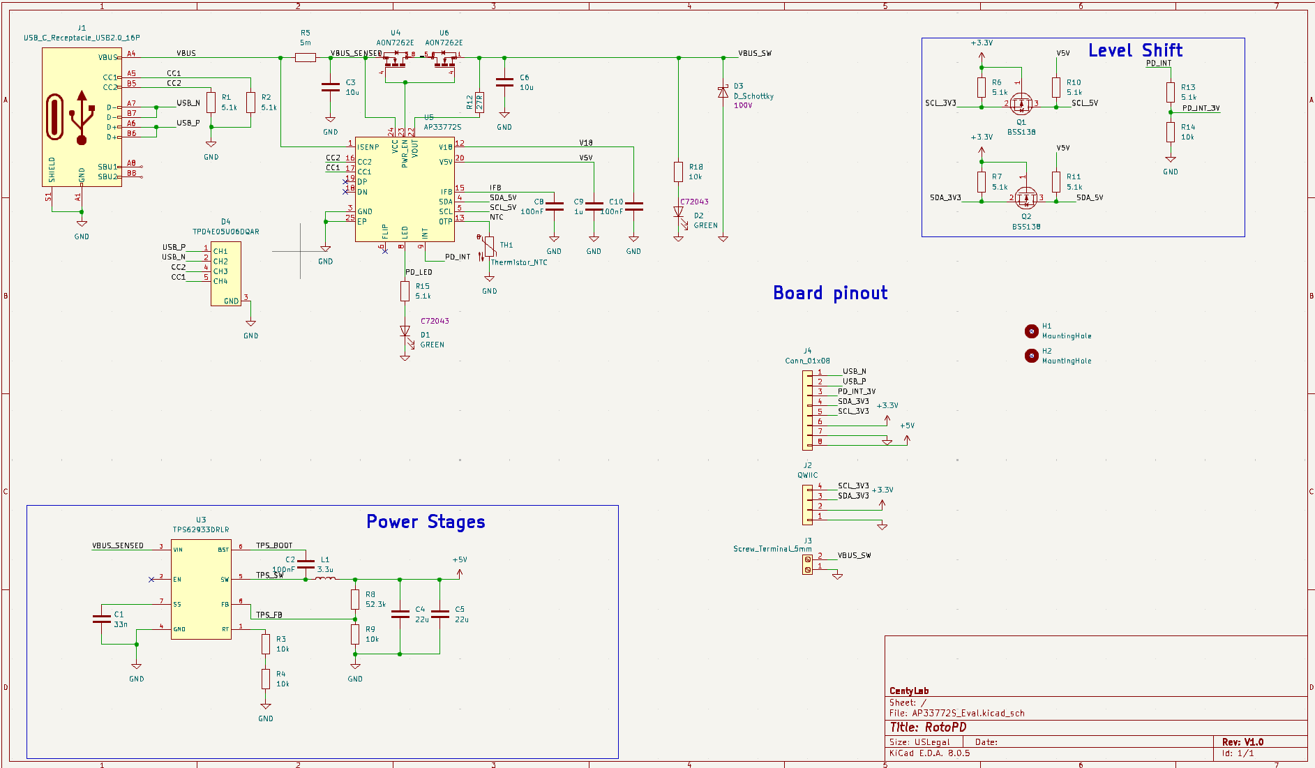
- Built-in chip: AP33772S
- Operating voltages: from 3.3 to 30V
- Maximum current: 5 A
- Maximum power: 150W (30 V at 5 A)
- Configuration: via I2C
- Connectors: USB Type-C, headers, Qwiic, STEMMA QT
- Weight: 4 g
Features
- Input and output voltage range of 3.5-30V at 5A max
- On board buck for 5V output at 2A max, 0.5A continous
- Support Qwiic or STEMMA QT in both 3.3V and 5V I2C
- Support PD3.1 EPR/AVS Up to 30V and SPR/PPS Up to 21V
- Certified USB PD3.1 v1.6 TID: 10062
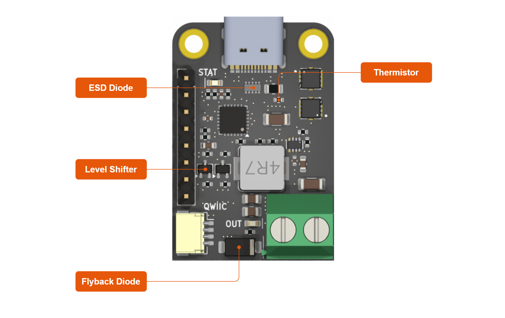
- Integrated ESD and flyback diode protection
- Integrated VBUS voltage monitoring
- Integrated NTC temperature monitoring
- Integrated VBUS switch gate drivers (back-to-back NMOS)
- Support LED Indication for Different Negotiation Results
EPR/AVS Power Supplies
As the technology is getting more adoption, as Dec 2024, here are some charger/power bank reported to provide AVS voltage adjustment.
AMEGAT Powerbank 140W (No longer recommend)
Demo
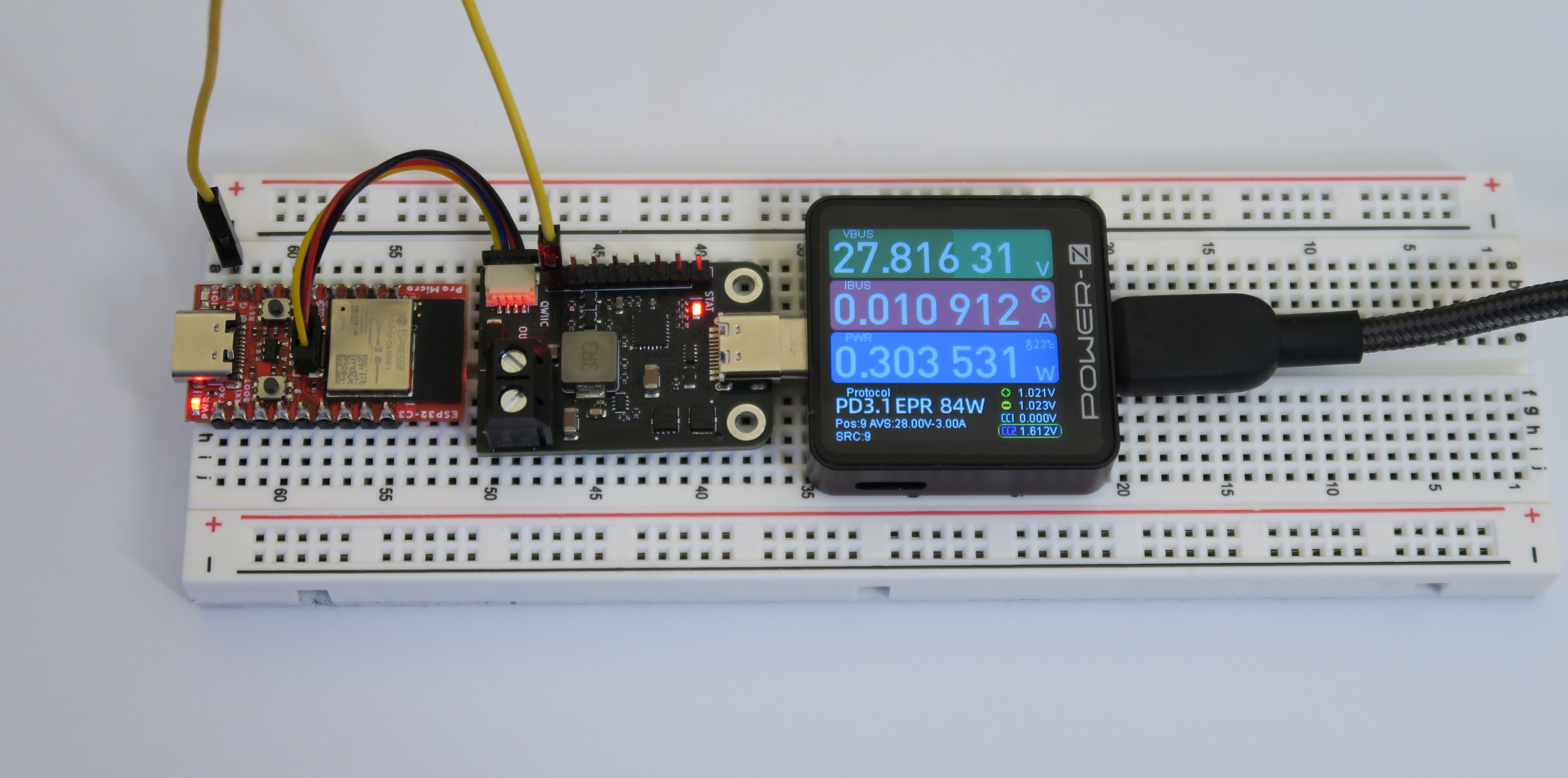
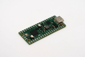
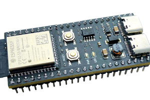
AVSFixed example with Sparkfun Pro Micro ESP32-C3. We are requesting AVS 28V.


 Marco Tabini
 EEEngineer4Ever
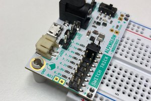
 Alpenglow Industries
Puzzled by how this works with PD voltages below 5V given the input to the buck converter will have to be above 5V to give 5V output? Will the '5V' output just follow the input in the range 3.5V - 5V, or will it cut out altogether? I've not yet wired the I2C to mine, but the 5V output does seem fine at the 5V vbus default (4.9V on '5V out' versus 5.0V on '+' output.