 John Anderson
I built the "Atari" workstation to program Microchip AVR microcontrollers that support UPDI programming. I use these microcontrollers in various projects I build for fun.
On the back of the workstation, there is a 6 pin aviation style connector. It is the programming port for the AVR UPDI interface.
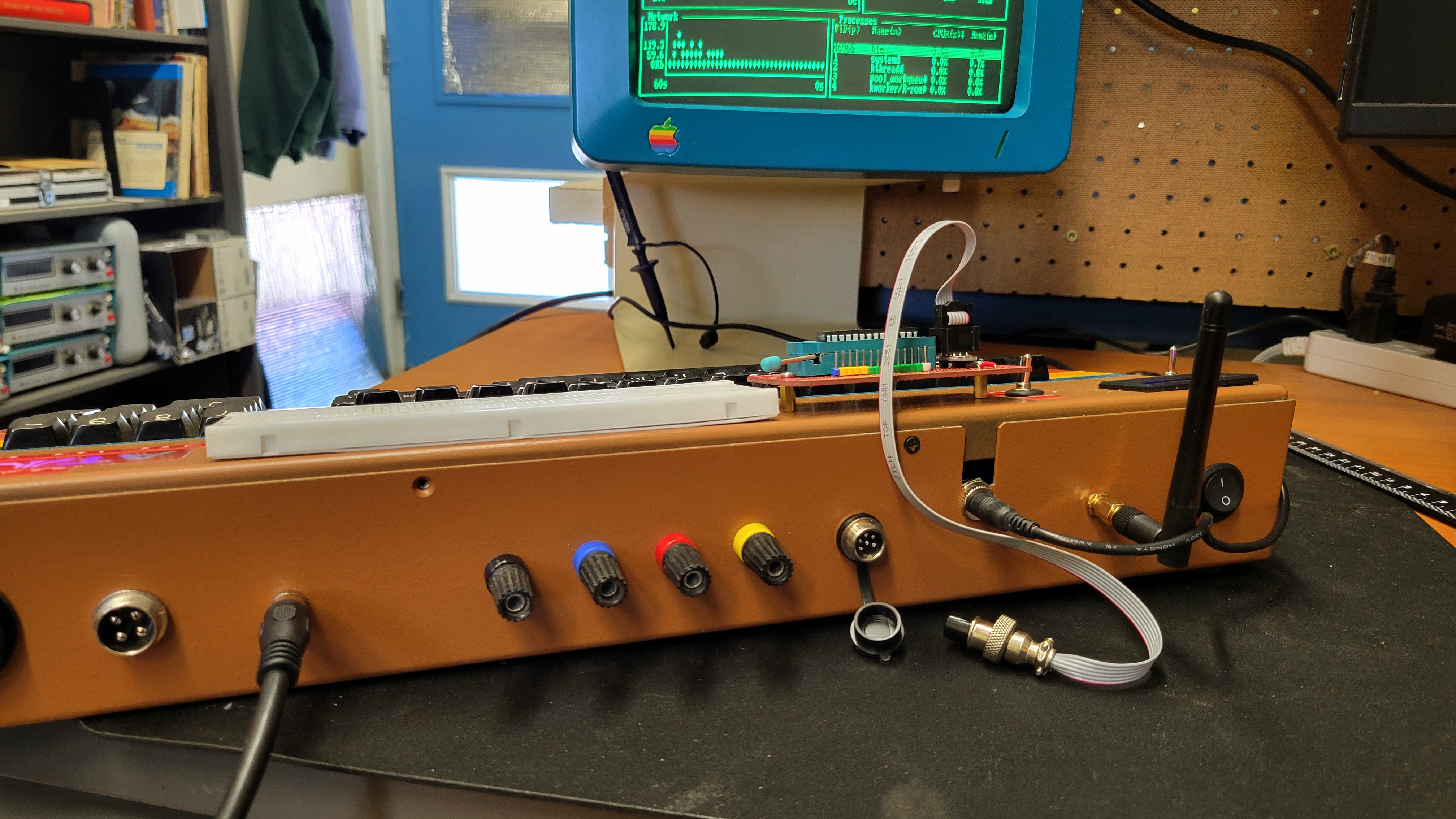
Various cables with different connectors can be built. This one has a standard AVR ISP 6 pin IDC layout. So, it can work with existing AVR based board with an ISP connector.
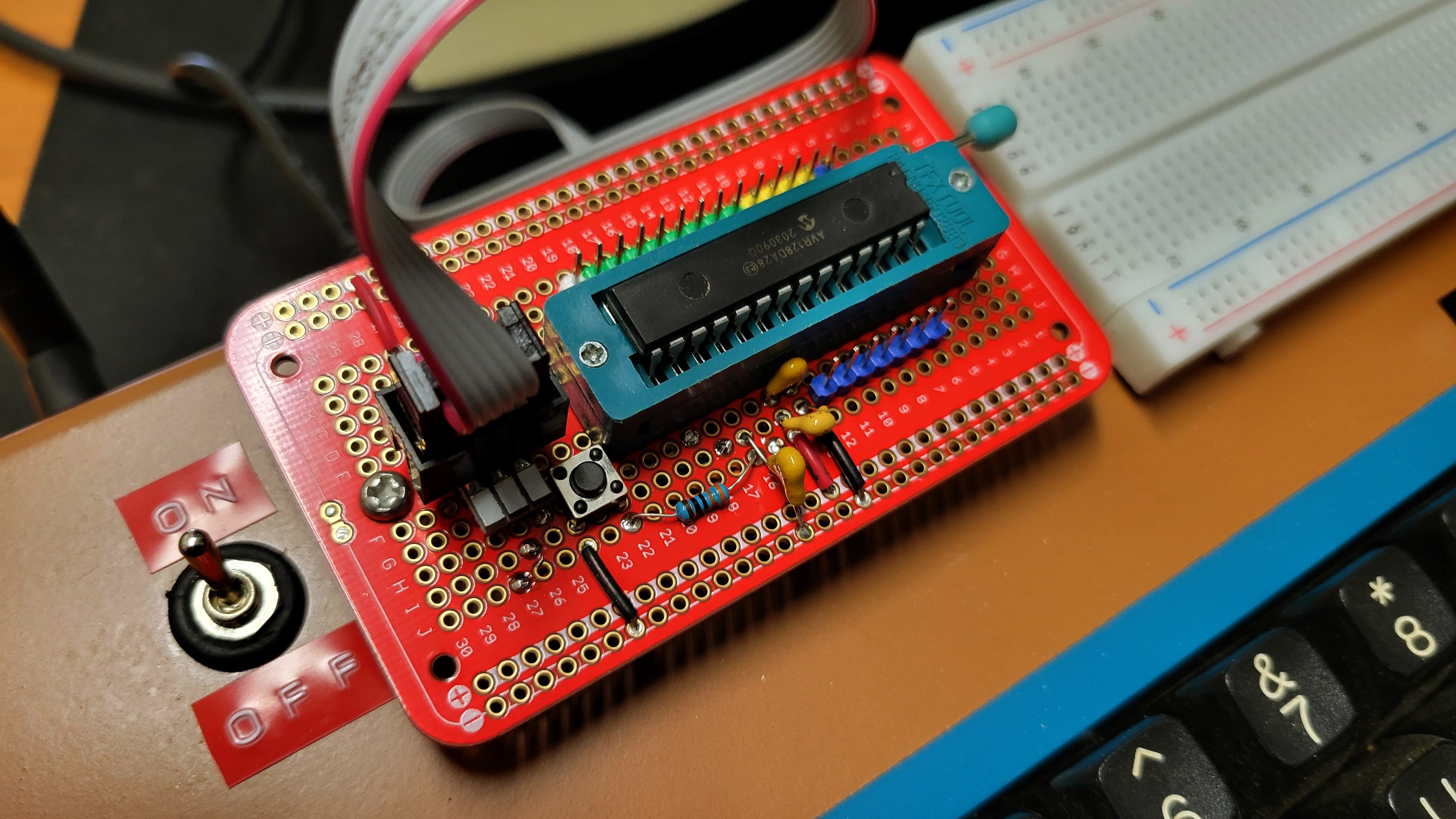
The soldered protoboard mounted on the face of the workstation is for AVRxxxDA28 and AVRxxxDB28 DIP parts. Different protoboards can be built and mounted there for other AVR target processors.
For more detailed information about how this is connected to the Raspberry PI inside the case, checkout this link to a document describing a Raspberry PI 4 model B Development Platform for avrOS on my github page.
The "Atari" workstation has one addition feature for this AVR UPDI interface. The voltage of the power supplied to the programming interface is selectable between 5v and 3.3v.
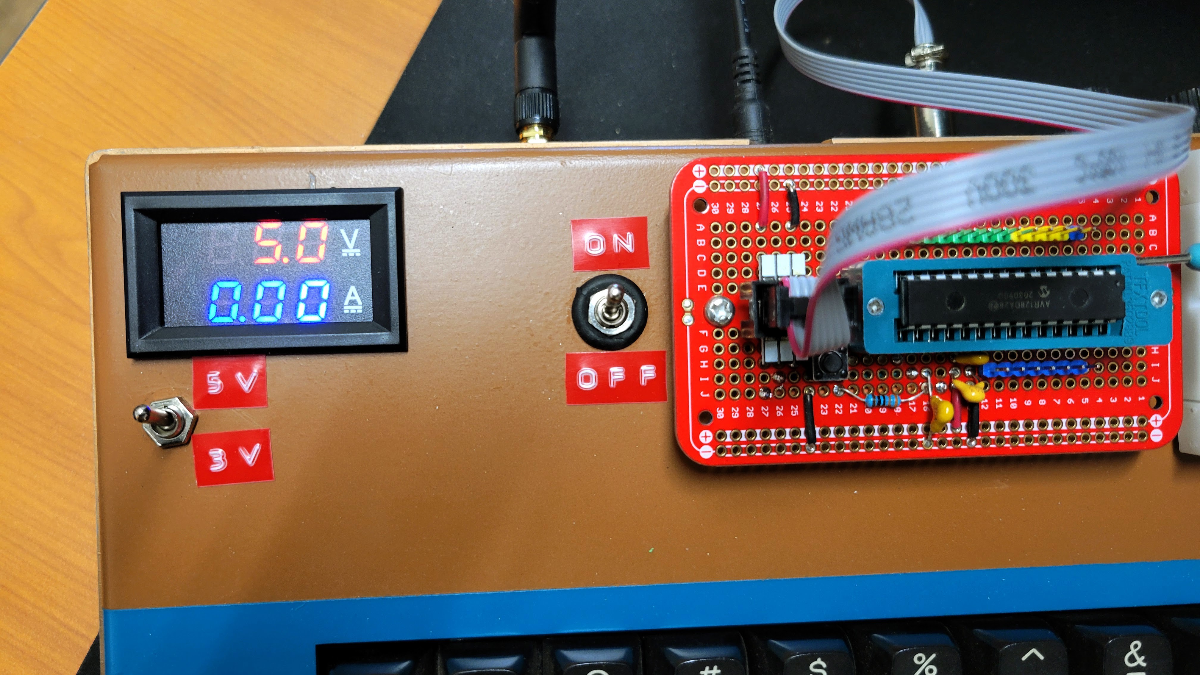
This requires an additional level shifter to be added between the PI and the programming port. In addition, I added a volt/amp meter to display the voltage and current supplied on that port.
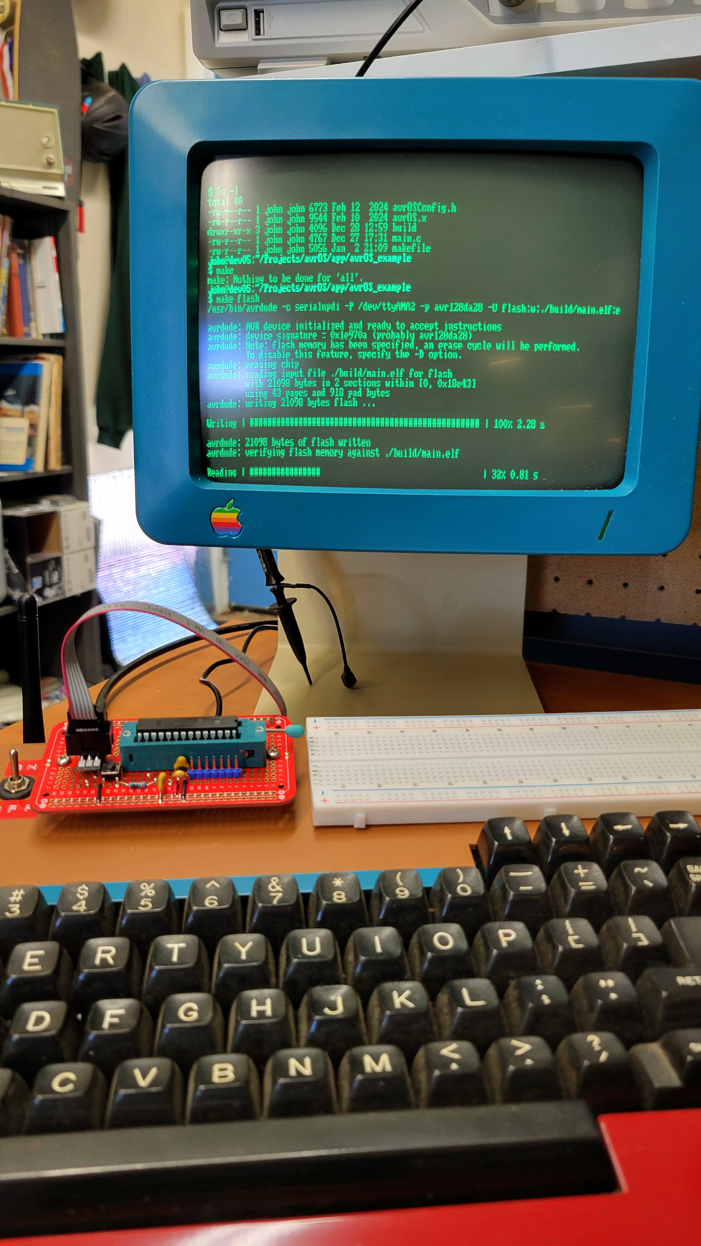
With all of this setup and connected, I can program AVR DA parts.
Discussions
Become a Hackaday.io Member
Create an account to leave a comment. Already have an account? Log In.